Do you have a question about the ECKELMANN Virtus 5 Series and is the answer not in the manual?
Explains warning signs, symbols, and text formatting for safety and clarity.
Details how hazard warnings and general instructions are presented in the manual.
Outlines necessary qualifications and training for personnel handling the system.
Defines the specific applications for which the Virtus 5 series controllers are designed.
Lists essential safety rules for electrical work as per DGUV Regulation 3.
Provides information on ESD sensitivity and handling guidelines for components.
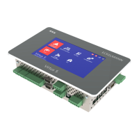
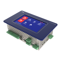
Describes the intended use, models, and core functions of the Virtus 5 series system centres.
Explains the process of upgrading system centre expansion stages using a license key.
Details the physical inputs, outputs, and interfaces of the system centre.
Lists the primary tasks and functions performed by the system centre.
Compares the functions and features of different expansion stages of the Virtus 5 series.
Covers the initial start-up and restart procedures for the system centre controller.
Explains how to configure the E*LDS system using the LDSWin PC software.
Details the controller's capabilities for monitoring E*LDS components on the CAN bus.
Describes the process of monitoring Modbus-connected devices and supported nodes.
Explains the configuration and use of digital inputs for monitoring and alarms.
Details the system centre's relay outputs for alarms, AUX functions, and week timers.
Describes the M-bus interface used for capturing energy, gas, and water consumption data.
Explains how the system centre collects, lists, and prioritizes alarms and messages.
Introduces the energy management functions, including the Load Shedding Manager.
Describes accessing temperature archives for HACCP compliance and data archiving.
Provides essential safety and procedural information for installing the system centre.
Details the default settings for DIP switches required for normal operation.
Gives instructions on the correct and incorrect methods for handling COMBICON connectors.
Explains the procedure for installing and disconnecting spring terminals.
Describes the DIN rail mounting of SIOX extension modules.
Explains how to connect E*LDS components to the system centre via CAN bus.
Details the Modbus connection for integrating RS485 controllers.
Describes how to connect M-bus meters using gateways.
Explains the connection and configuration of a GSM modem for remote maintenance and alarms.
Outlines the procedure for powering on the system centre.
Describes methods for configuring the E*LDS system using a service PC.
Explains how to update the system centre's firmware to newer versions.
Provides a visual diagram of the system centre's connections and terminals.
Details the terminal connections for the 230 V AC power supply.
Explains the terminal assignments for the 230 V AC digital inputs.
Details the terminal assignments for the 230 V relay outputs (PRIO1, PRIO2, AUX).
Explains the terminal assignments for the CAN bus interfaces.
Details the terminal assignments for connecting SIOX extension modules.
Explains the terminal assignments for the COM3/Modbus (RS485) interface.
Provides a comprehensive overview of all communication interface terminal assignments.
Shows a diagram illustrating the connections and terminals of the SIOX extension module.
Details the terminal assignments for the 230 V AC relay outputs on SIOX modules.
Explains the terminal assignments for the 230 V AC digital inputs on SIOX modules.
Covers operation and access to the system centre directly via the device interface.
Details the procedure for logging into and unlocking the system centre.
Explains how to remotely control E*LDS components using terminal mode.
Outlines the possibilities for remote operation of the system centre via networks.
Describes how to control the system centre remotely using a web browser and Virtus Control Desk.
Explains how to operate the system centre remotely using VNC software.
Provides instructions for safely dismantling and removing the equipment.
Gives guidance on the environmentally friendly disposal of the system centre and its components.
Lists the electrical specifications, including voltage, power, and input/output ratings.
Covers the mechanical specifications of the system centre, including dimensions.
Details cut-out dimensions for panel installation.
Lists part numbers for system centres and SIOX extension modules.
Details the available accessories for the system centre.
| Power Supply | 24 V DC |
|---|---|
| Protection Class | IP20 |
| Operating Voltage | 24 V DC |
| Interfaces | Ethernet, USB, RS-232, RS-485 |
| Digital Outputs | 8 |