7.1.4 Terminal assignment of the CAN bus terminals
The terminals for the connection to the first CAN bus segment CAN1 (standard) and second CAN bus segment
CAN2 are located on the device at the bottom. See chapter CAN bus - Connection of E*LDS Components for
further details about the range of functions of the two interfaces.
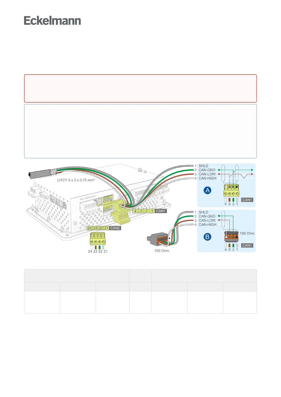
Connection to the CAN bus, shown here using the first CAN bus segment (CAN1) as example. This also
applies for the second CAN bus segment (CAN2).
CAN1 - First CAN bus segment
Standard
CAN2-SecondCANbussegment
VSC5110/VSC5510only:Repeaterfunction
Terminal No. Function Wire colour Terminal No. Function Wire colour
4
3
2
1
CAN-HIGH
CAN-LOW
CAN-GND
SHLD (Shield)
white
brown
green
shield
24
23
22
21
CAN-HIGH
CAN-LOW
CAN-GND
SHLD (Shield)
white
brown
green
shield
For details, see CAN bus - Connection of E*LDS Componentsandoperatingmanual“Basics and general
safety and connection instructions”.
DANGER
Warning about dangerous electrical voltage! If mains voltage is connected to the CAN bus
terminals, this will result in the destruction of all components connected to the CAN bus!
CAN bus supply lines must be shielded (cable type: LiYCY 2x2x0.75 mm
2
)! As a general rule, care
should be taken to ensure that signal cables and cables carrying mains voltage are routed in separate
cable channels.
Wiring Variant A: Device is a node in a CAN bus segment with other devices before and after this, no
terminating resistor required.
Wiring Variant B: Device is at the start / end of a CAN bus segment, terminating resistor required.
Recommendation:UseoftheterminalsetforCANbustermination;seechapterZubehör für
Systemzentrale.