Configuration of the jumper J1
The jumper J1 is located centrally under the casing cover of the SIOX extension module. The following settings
are possible:
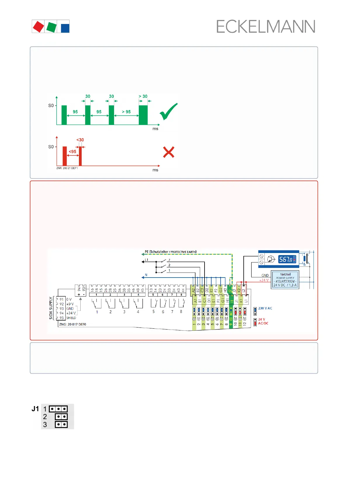
Special case: Acquisition of 24 V DC meter pulses (S0 interface)!
Conditions:
1. GND of 24 V DC must be applied at the terminal level (A2 .. L2)!
2. For counting S0 pulses, these must be at least 95 ms apart from each other. Faster pulse
sequenceswillnotbedetected;thepulsewidthmustbeatleast30ms.
Warning about dangerous electrical voltage! Danger of electric shock! The configuration of the
jumpers must always be performed when no voltage is present and with the connectors at the inputs
(terminals A1, A2/ ... /L1, L2) detached as a voltage of 230 V AC can be present at these terminals
undercertaincircumstances!If230VACisappliedtoaninputthathasbeenconfiguredfor24VAC,
this results in destruction of the extension module (SIOX)!
Wiring of the digital inputs:
230 V AC: The N conductor must be applied at a terminal level (A2 .. L2)!
24 V AC/DC: If 230 V AC and 24 V AC/DC inputs are needed on a SIOX module, these must be
separated by an input connected to PE!
Note: In the example, the first 3 digital inputs (channels A / B / C - 230 V AC) of the SIOX extension
module are used for installation monitoring and the last channel (L - 24 V AC/DC) is used as SO
energy meter.
 Loading...