•
•
•
•
•
•
•
•
•
•
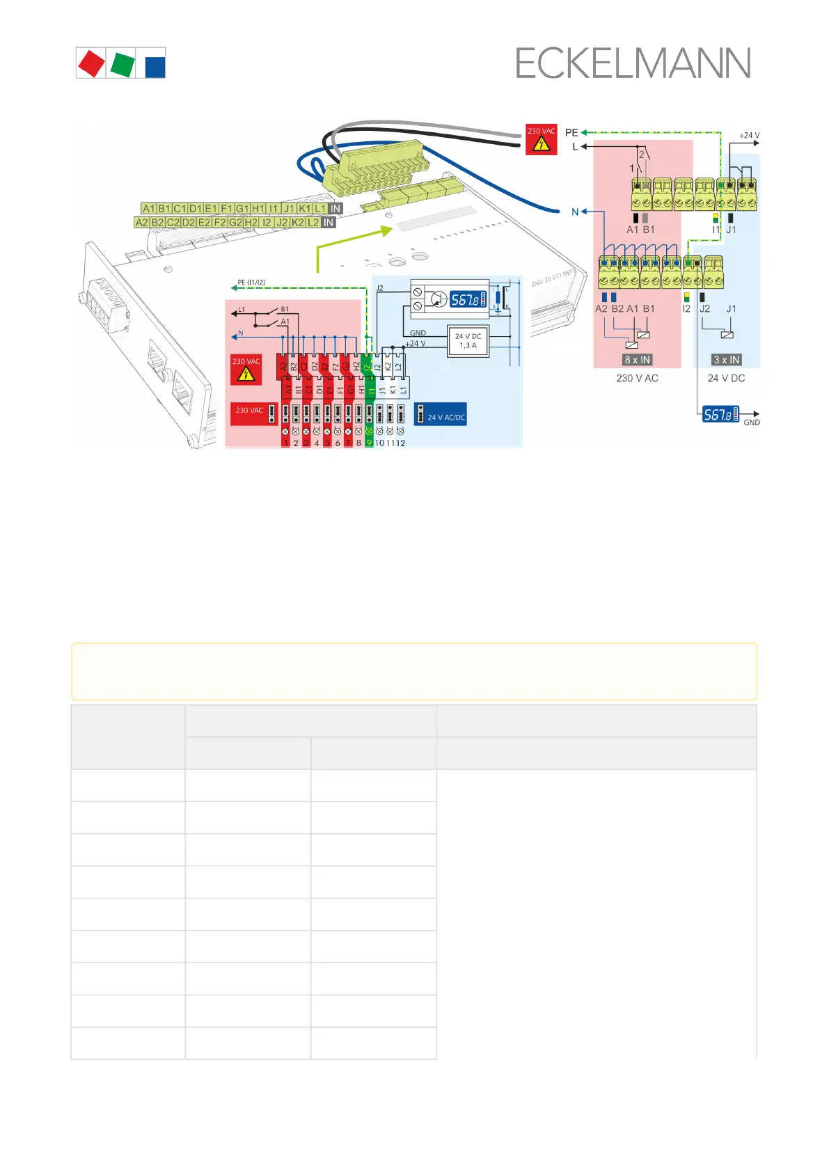
Note: The digital inputs of the SIOX extension module in the example are used / configured as follows:
The first 8 digital inputs A2..H2 have been configured for 230 V AC using jumpers.
Ideally, A2..H2 are connected to N.
The first two digital inputs A1/A2 and B1/B2 are used for system monitoring.
The ninth digital input I1/I2 is connected to PE for the electrical isolation of the high / low voltage side.
The3digitalinputs10..12havebeenconfiguredfor24VAC/DCusingjumpers.
Thetenthdigitalinput(J1/J2)isusedas24VDCenergymeter.
Note: A power supply (part number KGLNT23024) may be required for the supply of the meter.
Digital input Terminal No. Function
Without switch * With switch *
1
A1, A2 50, 51
Alarm and message inputs (e.g. for detection of
external alarms)
Meter inputs for energy, gas, water and event
Meter inputs for recording of the high and low tariff
(HT/LT)
Synchronisation inputs for acquisition of the
synchronisation pulse of the power company
2
B1, B2 52, 53
3
C1, C2 54, 55
4
D1, D2 56, 57
5
E1, E2 58, 59
6
F1, F2 60, 61
7
G1, G2 62, 63
8
H1, H2 64, 65
9
I1, I2 66, 67
Detailed safety instructions and information for the configuration of the jumpers for the digital inputs are
provided in chapter SIOX - configuration of the jumpers.
 Loading...