Section 15. Multi Function Display (MFD) Eclipse 5OO Systems Manual
Copyright © — Eclipse Aviation Corporation
Version 2.0 April 2007 355
100%. An amber band extends from 100% to 101%. A red band begins at the
maximum continuous limit of 101%.
The digital value and moving tape are white for N
1
values in the green band, in amber
for N1 values in the amber band, and in red for N1
values above the RPM limit. If the
RPM exceeds the limit for 20 seconds, an ENG EXCEEDANCE warning message
appears.
A blue bug and blue digital readout between the left and right N1 tapes display the N1
target calculated by the ACS for the mode of flight.
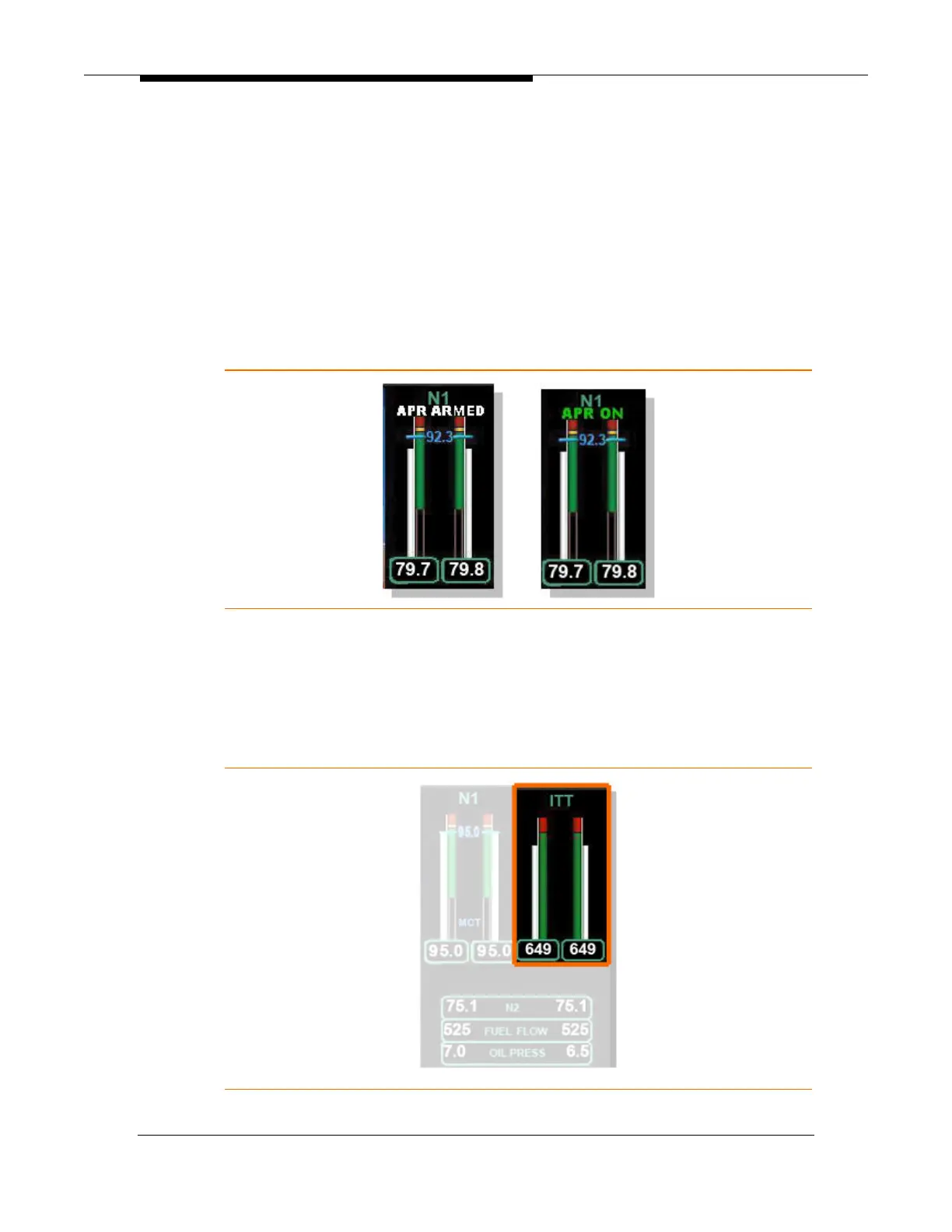
With the throttles advanced to the takeoff setting the state of the Automatic Power
Reserve (APR) is displayed above the N1 tapes as either APR ARMED (white) or
APR ON (green).
Figure 238. APR Indications
When the throttles are reduced on climb to maximum continuous thrust as calculated
by the ACS, blue MCT text appears at the lower portion of the tape that is associated
with the blue N1 bug.
15.5.2 Indicated Turbine Temperature (ITT)
Figure 239. ITT Display