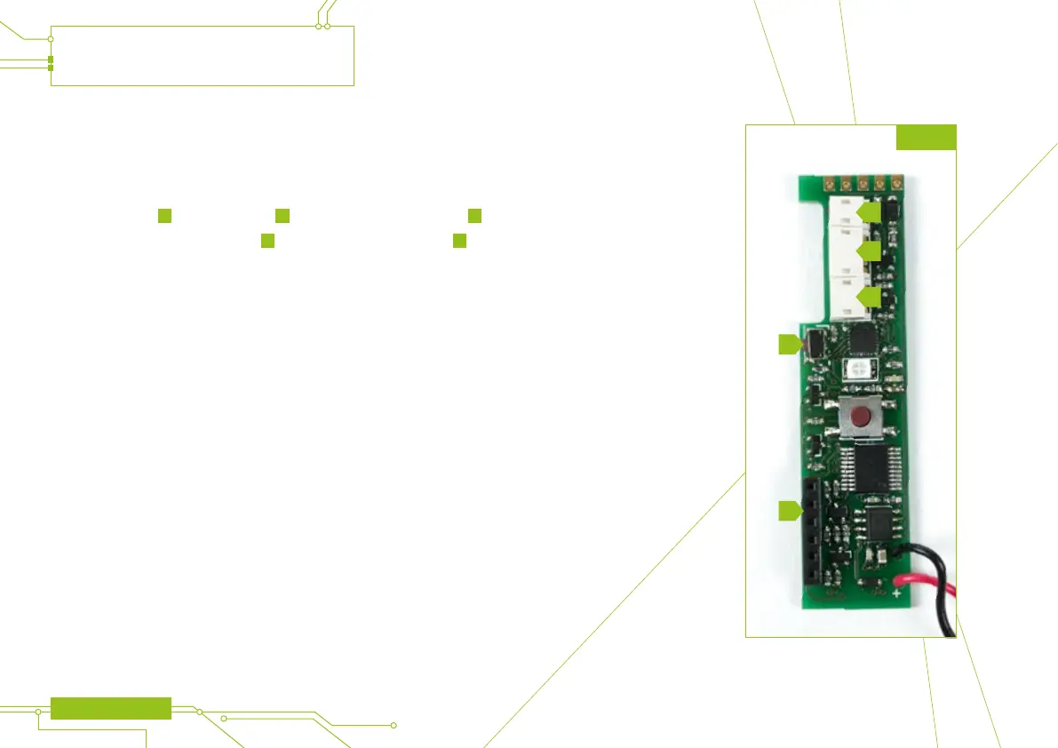
THE ETEK5 CIRCUIT BOARD
The ETEK5 circuit board sits within the frame and is accessible by removing the
rubber grips (see page 29 to learn more).
There are three sockets on the ETEK5 circuit board (see gure 5A), the ETEK5
solenoid connector
A
, the BS connector
B
and the micro-switch connector
C
.
There is also a tournament lock button
D
and the OLED board connector
E
.
Information on the tournament lock button functionality can be found on page 24.
1 When the ETEK5 is turned on, the Breech Sensor is automatically enabled.
2 The colours displayed during the power up sequence may vary depending on the region the marker
was originally purchased.
USING THE ETEK5
10 ETEK5 MANUAL
FIG 5A
A
B
C
D
E