USING THE ETEK5
THE ETEK5 OLED BOARD
The ETEK5 OLED board connects to the existing ETEK5 circuit board, which sits
within the frame and is accessible by removing the rubber grips (see page 29 to
learn more).
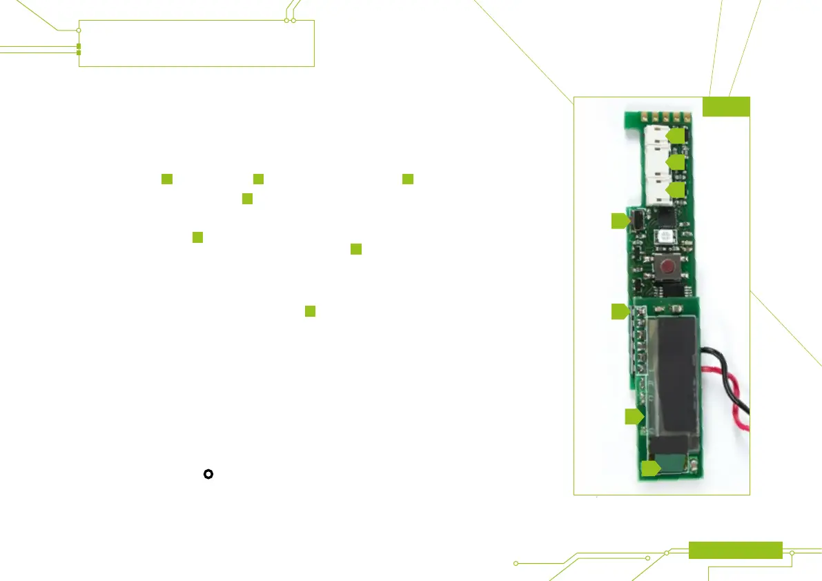
There are three sockets on the ETEK5 circuit board (see gure 6A), the ETEK5
solenoid connector
A
, the BS connector
B
and the micro-switch connector
C
.
There is also a tournament lock button
D
.
Information on the tournament lock button functionality can be found on page 24.
The OLED board (labelled
F
gure 6A) attaches to the standard ETEK5 board via
the connector at the bottom of the ETEK5 circuit board (labelled
E
gure 6A).
The mating connector sits to the upper left of the OLED board, which sits inline with
the ETEK5 circuit board and extends downwards.
Before installation into your ETEK5 frame make sure you gently remove the OLED
display’s protective lm using the green tab (labelled
G
gure 6A).
For further details of how to install the OLED board see page 29.
1 When the ETEK5 is turned on, the Breech Sensor is automatically enabled.
2 By continuing holding down the
button when turning on the ETEK5 OLED board the software
version number will be displayed.
ETEK5 MANUAL 11
FIG 6A
A
B
C
D
E
F
G