Do you have a question about the Ecom ST and is the answer not in the manual?
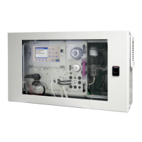
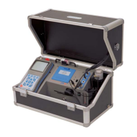
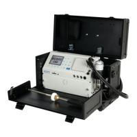
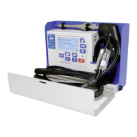
Identifies and illustrates the main physical components of the device.
Details the various input and output ports and their functions.
Explains the function of each key on the device's control panel.
Covers communication ports like USB, RS485, and Ethernet.
Describes the USB connection for PC data transfer and software.
Details the RS485 interface for Modbus RTU communication.
Explains the Ethernet connection for network integration and Modbus TCP.
Describes the 8 analog output channels and their pin assignments.
Explains the functionality and benefits of the unheated sampling system.
Details the heated sampling system and its advantages for specific measurements.
Covers the use of SD cards for saving measurement data.
Provides dimensional drawings and instructions for wall mounting.
Details the process and considerations for installing the device in a rack.
Lists essential checks and steps before performing a measurement.
Explains how to perform flue gas analysis and select fuel types.
Describes the different display screens for measurement results and data.
Details how to perform and interpret draught measurements.
Explains the system's protection mechanism against CO sensor overload.
Configures Modbus, timing, and data logging functions.
Details Modbus communication settings and device addressing.
Explains how to configure automatic timing and interval settings.
Guides on setting up the 4-20mA analog output signals.
Explains how to use the data logger function with an SD card.
Details connecting the device to a PC for data transfer.
Describes connecting to PC using ecom-DAS NT2 software via USB.
Explains PC connection using ecom-DAS 5 software via USB.
Information on integrating with existing software using ecomModbus.
Instructions for checking and changing the fine dust filter.
Discusses sensor calibration, monitoring, and reference values.
Provides procedures for calibrating the gas sensors using calibration gas.
Step-by-step guide for removing and reinstalling device modules.
Recommendations for cleaning and maintaining the probe and tubing.
Mentions the regular changing of the PTFE filter in the probe head.
Details the specifications for each measured parameter.
Details calculated parameters, their ranges, and the principles used.
Provides additional technical specifications like power supply, dimensions, and weight.
| Brand | Ecom |
|---|---|
| Model | ST |
| Category | Measuring Instruments |
| Language | English |