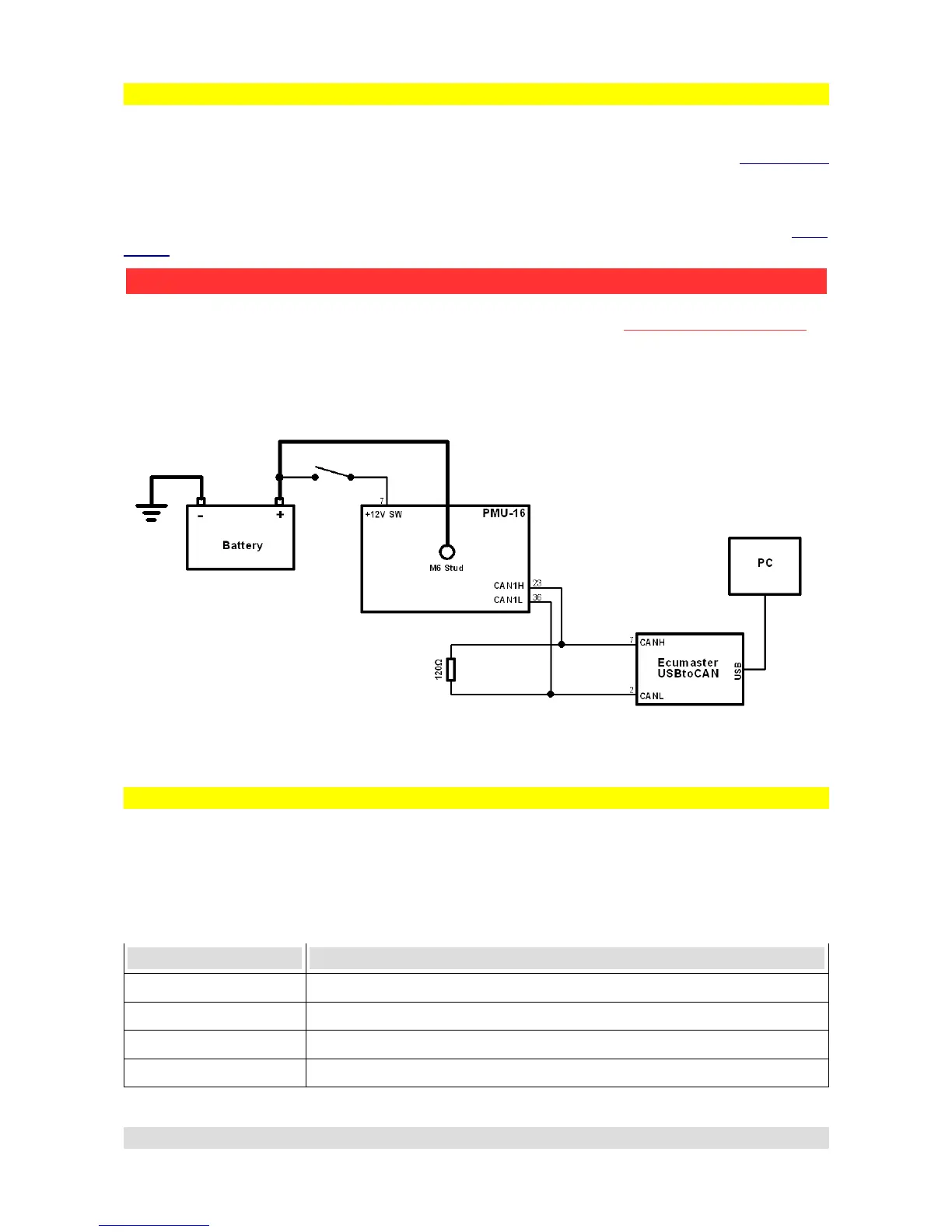
Connecting USB interface, wiring schematics
To connect PMU to PC, CAN1 CANbus must be used. This is the CAN provided for us for PC
communication. To wire the USB - CAN interface, CAN1H and CAN1L pins (See PMU Pinout
section) must be used. Twisted pairing is also recommended. CANbus must also be terminated at
both ends of the bus. ECUMASTER USBtoCAN is equipped with one terminator that can be
switched on or off (See ECUMASTER USBtoCAN interface section).
If the Interface is connected, PMU must be supplied with power, both on the +12SW Pin (See PMU
Pinout section) and the M6 stud.
Here is a simple diagram of USB connection, please note that it assumes that the second
terminator is applied by the USBtoCAN interface:
PMU status
PMU device is fitted with LED that signals status of the PMU device.
Picture showing the LED location:
There are 6 possible states of PMU LED:
Color Status
Green Continuous Device is active
Orange Continuous Device is active and connected to PC
Green Flashing Slowly Device is waiting for Firmware Upgrade
Orange Flashing Slowly Device is performing Firmware Upgrade and is connected to PMU
Page 13
PMU - PC communication
ATTENTION !
Ground wire connection between USBtoCAN and PMU-16 can be DANGEROUS!
Ground connection is only allowed if devices before connecting have the same ground potential.
Potential difference can be checked by using voltometer between corresponding grounds.