Output Pins
There are 16 output pins for you to use, 10 25A pins and 6 15A pins. They can be also used in
parallel to increase current capacity (See Using output pins in parallel section)
All Pins are equipped with over and under current protection, short circuit protection, as well as
thermal protection. In case of any of this scenario happening, the output pin will be shut down and
apropriate message will be displayed in the PMU Client and the PMU itself.
For 25A Output Pins, Soft Start is available and PWM with Duty Cycle control (See PWM section)
Input Pins
There are 16 input pins for you to use as well as a separate +5V Pin to provide power for Analog
Inputs such as rotary switches, or analog sensors.
PMU TEMPERATURE, PLACEMENT AND LOAD BALANCING
PMU Placement
PMU should be located in a place that protects it from weather conditions, road debris and road
hazard. Even though PMU case works as a radiator, it is also recommended to place PMU
somewhere where heat can be dissipated easily, preferably with good airflow.
PMU Temperature
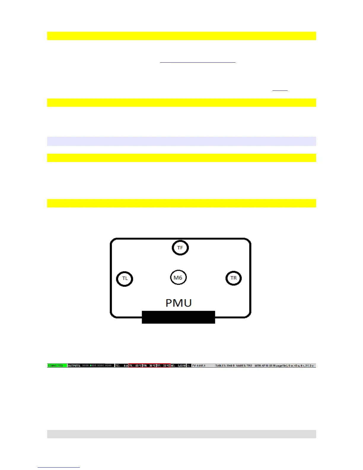
PMU has three thermometers located on its board to independently measure temperature in three
separate places.
There are two places where temperature can be checked in PMU Client, first is the status bar and
the values TL, TR, TF (Temperature Left, Temperature Right, Temperature Flash):
Second is the PMU window which can be accesed by double clicking PMU on Tree View:
Page 28