WIRING
Basic diagram
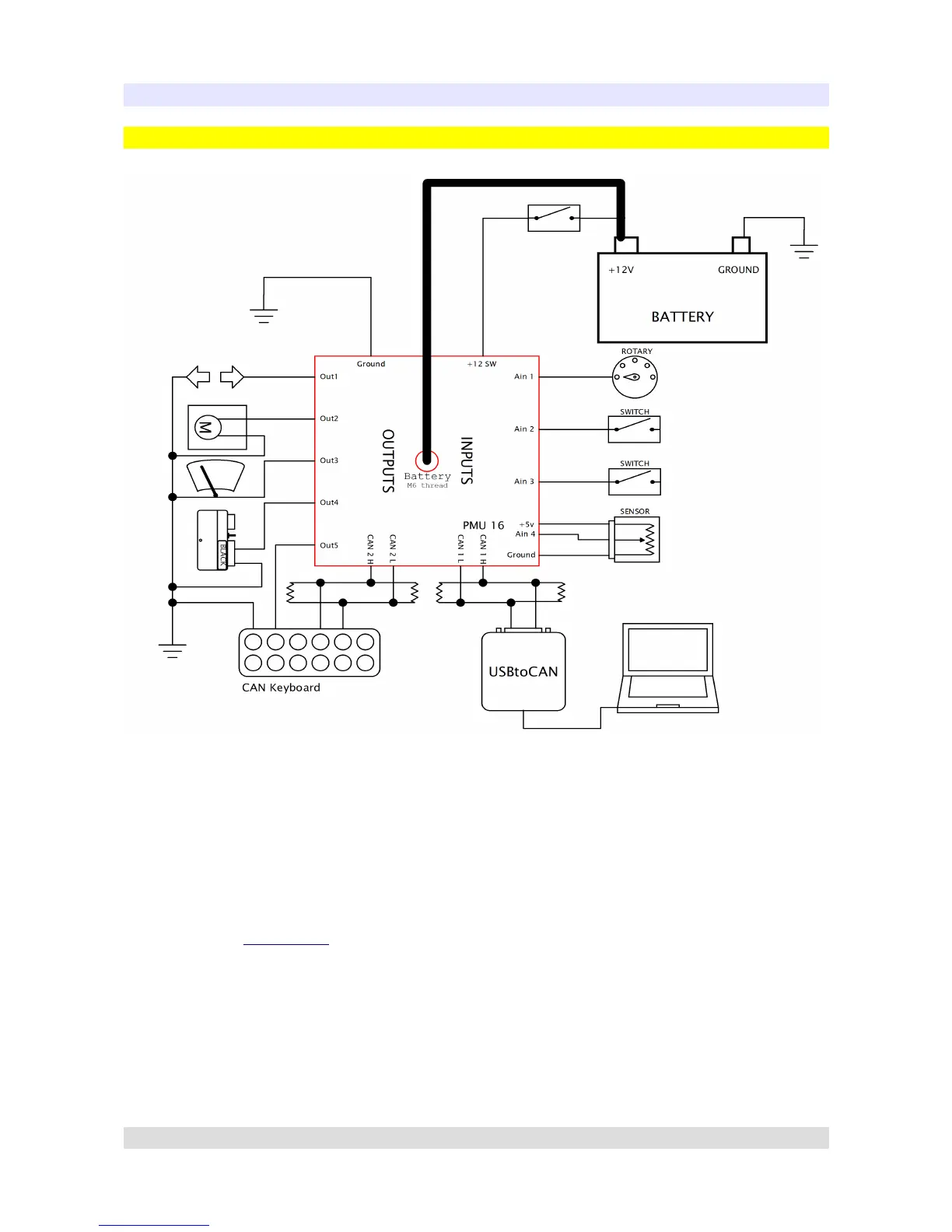
This is the basic PMU communication and connection diagram which contains few key elements:
• PC Communication takes place on CAN 1 as this is the CAN specified to use for PC
connection.
• CAN 1 has two 120 Ohm terminators on CAN bus. They are necessary, as PMU does not
provide termination on CAN 1.
• CANbus Keyboard is connected to CAN 2.
• Power to PMU is supplied in two ways: First using the ignition which connects to +12SW
Pin (See PMU Pinout section), second using positive battery terminal which connects to M6
Bolt located on PMU case.
Page 31