150
support@edgeovens.com Technical Support: +1 (724) 628 3050
SERVICE
PART FAILURE VERIFICATION
CONTROLS AND ASSEMBLIES (CONTINUED)
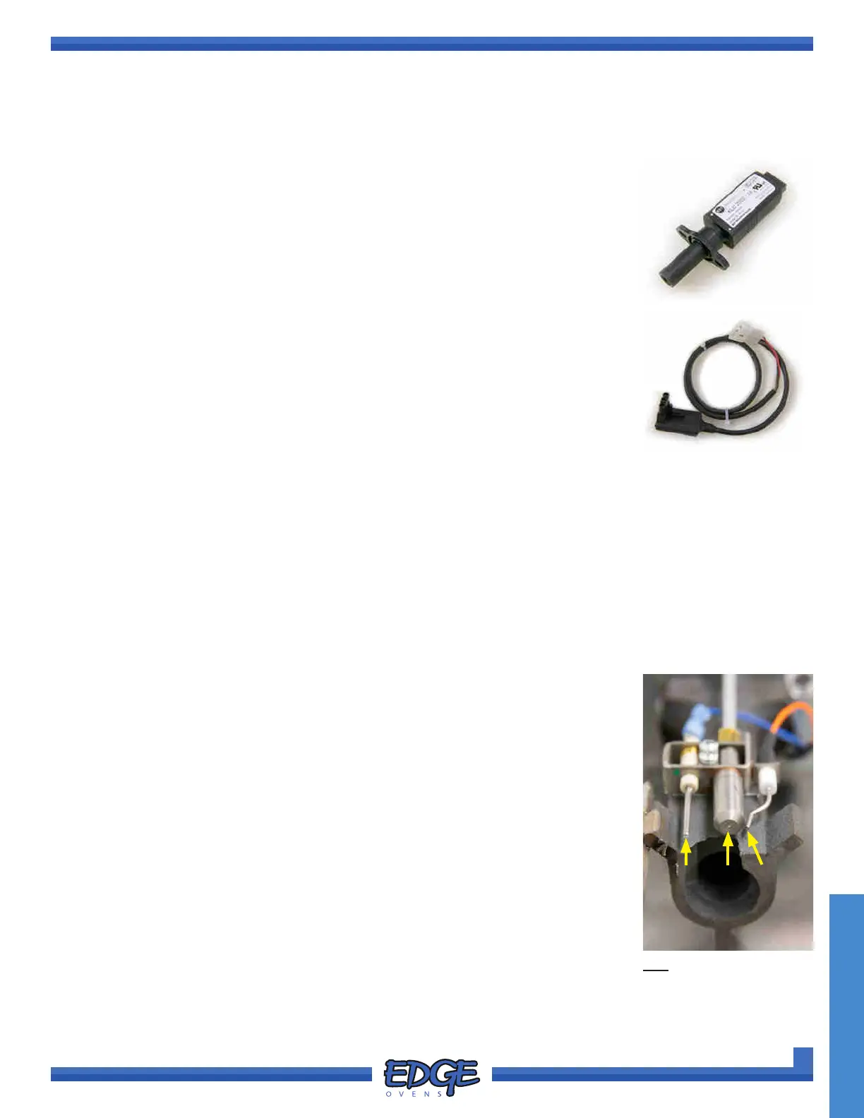
The optical ame detector is positioned on the burner tube so that it has a clear line-
of-sight that intersects with the burner ame. The body of the detector MUST be fully
seated in the ange.
The detector inspects the light received to ensure that it is not an articial ame.
When a ame is detected, the sensor will return a μA signal, much like a standard
ame rod. Additionally, the detector houses a red LED that will ash very rapidly
(appearing more STEADY and brighter) during normal operation and while detecting
a ame.
• The detector requires 24VAC to operate.
• If the red LED is not illuminated DURING the ignition cycle of the oven (sparking
will be audible), verify this supply voltage is present on the Brown and Green/
Yellow wire. If supply voltage is PRESENT, replace the detector.
• If the LED does not maintain STEADY illumination with the ame visible in the
burner site glass, remove the detector and clean the lens with a cotton cloth or
lens wipe.
• Measure the ame signal in-loop (BLACK, SENSE terminal on Ignition Module). A
strong ame signal for this device is 0.7~0.9μA. If the signal is low or not present,
replace the detector.
• In the event the detector fails, the electrode Flame Rod may be connected until
a new detector can be installed. See Ignition Electrodes / Flame Rod section for
details.
OPTICAL FLAME DETECTOR
Buildup of soot and silica will cause ignition failures and ame detection problems (if
using the ame rod).
1. Visually inspect the ignition electrodes and ame rod for buildup, clean as needed
using a 220 grit sandpaper to clean the electrodes. NEVER use metallic materials
to clean the electrodes, this will degrade them.
2. The pilot head must also be cleaned. Failure to clean both the electrodes and the
pilot head is likened to cleaning only 1 post of an automotive battery; the failure
will rapidly reoccur.
3. If the condition is not improved by cleaning, please verify the electrical
connections of the burner. Igniter cable and the ame sense wire are connected
and the contacts are clean and secure. Also ensure the burner is grounded.
The signal produced by the ame rod and the control is relatively small. At
0.2~0.3μA, this is considered strong returning ame signal.
4. The ame rod is used as a back-up. The Optical Flame Detector (OFD) is the
primary ame detection device. The BLUE wire from the burner ame rod is
secured with a cable tie. Cut the cable tie and swap out the BLACK wire on
the SENSE terminal for the BLUE wire if ame rod operation is needed.
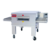
IGNITION ELECTRODES / FLAME ROD
1 2 3
KEY
1. FLAME ROD
2. PILOT HEAD
3. SPARK ELECTRODE
FIGURE 4-47