10
support@edgeovens.com Technical Support: +1 (724) 628 3050
SPECIFICATIONS
SINGLE STACK
A = 30.75” (781mm)
DOUBLE STACK
A = 30.75” (781mm)
B = 51.00” (1295mm)
TRIPLE STACK
A = 22.00” (559mm)
B = 35.25” (895mm)
C = 55.50” (1410mm)
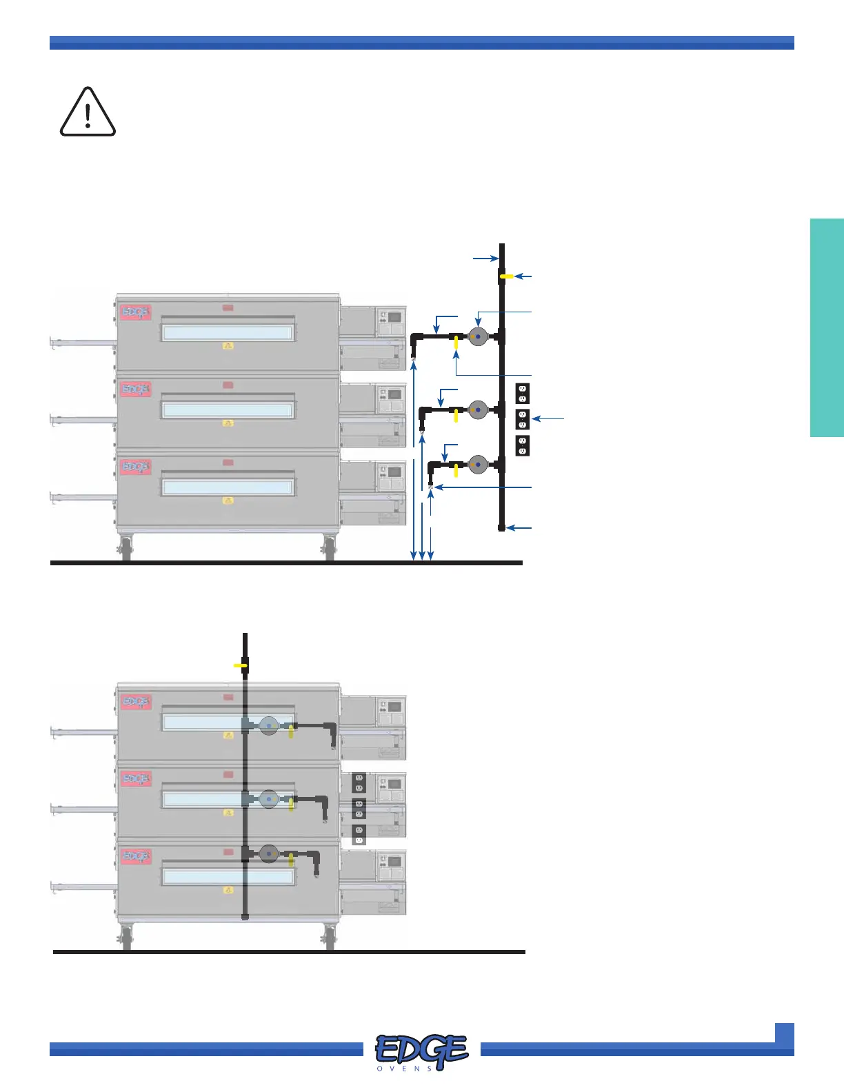
IMPORTANT
Utilities must be accessible when the ovens are in their installed position. Do not install
utilities behind the ovens. Incoming gas line MUST be positioned on the oven control
cabinet side.
As all kitchen situations vary, so may your installation. The below illustration is a best practice guide and should
be adhered to as closely as possible.
OUTLET HEIGHTS
BEST PRACTICE GAS & ELECTRICAL CONFIGURATION
C
B
A
2”
4”
6”
Main Gas
Shut-Off Valve
Capped 8”
Trap Line
Oven Gas
Shut-Off Valve
Minimum
Pipe Size 2”
3/4” NPT (Domestic)
3/4” BSP (World)
Electrical
Supply
Gas Pressure
Regulator
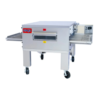
ACCEPTABLE INSTALLATION
UNACCEPTABLE INSTALLATION
*Minimum Clearance:
6 inches from combustibles on all sides