48
support@edgeovens.com Technical Support: +1 (724) 628 3050
INSTALLATION
FINAL CONNECTIONS
GAS CONNECTION
1. Before proceeding with the oven’s gas utility connection, verify the gas supply specications match the
listed gas type and gas supply requirements on your oven. (Example - Figure 2-114)
2. Install a exible quick disconnect gas hose as per the hose manufacturer’s installation instructions to each
oven deck. See “BEST PRACTICE GAS & ELECTRICAL CONFIGURATION” in the SPECIFICATIONS
section of the manual for recommended manifold conguration.
INSTALLATION WITHOUT A FLEXIBLE DISCONNECT GAS HOSE OR HARD PLUMBING IS NOT
RECOMMENDED AND WILL INVALIDATE THE OVENS WARRANTY.
3. For each oven deck, verify INLET GAS PRESSURE.
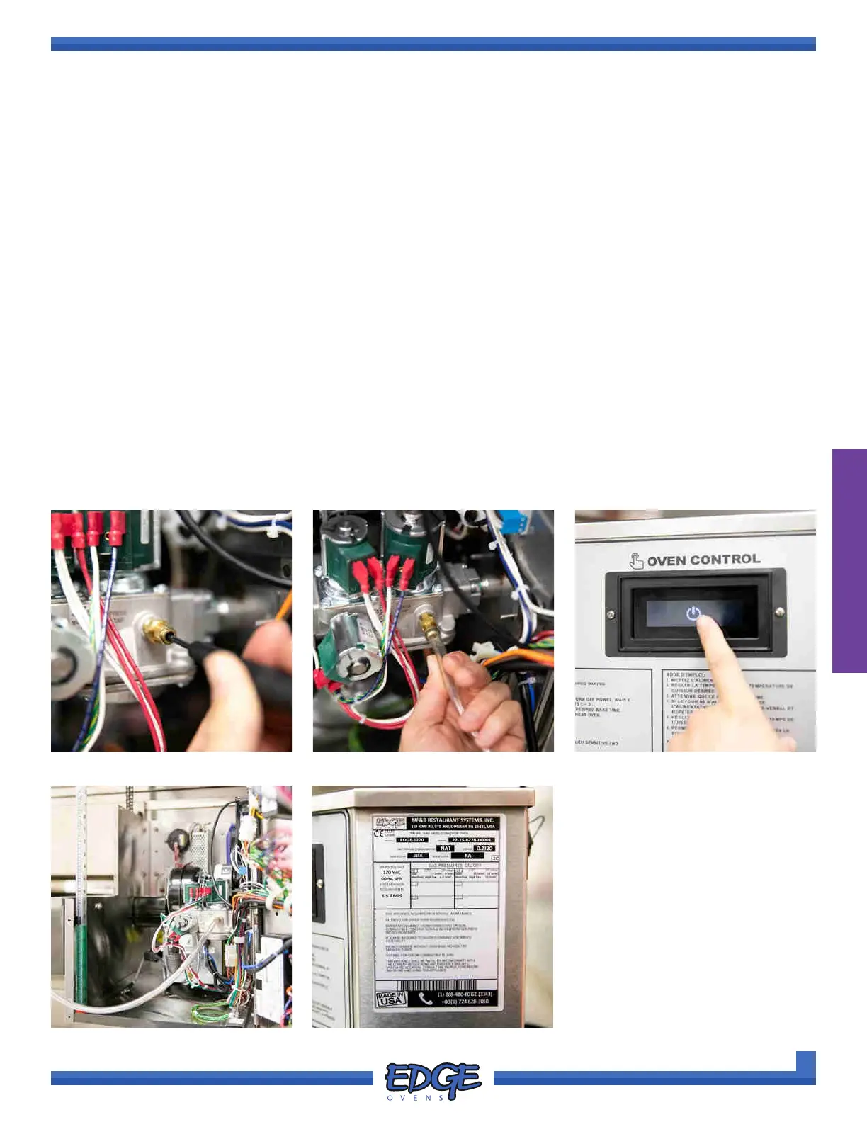
a. Before mounting your manometer tube on the INLET PRESSURE TAP (6) (Figure 2-109) on the side
of the gas valve, use a short straight-line slotted screwdriver to loosen the slotted brass at head screw
with approximately three counter-clockwise turns. (Figure 2-110)
b. Mount you manometer tube on the INLET PRESSURE TAP (6) Figure 2-111) and re up the oven.
(Figure 2-112)
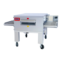
c. Gas inlet pressure must be veried with all ovens and gas appliances ON, to ensure adequate
supply pressure and volume (Figure 2-113). Recommended supply requirements can be located
on the oven data decal, located on the control cabinet side (Figure 2-214). Once tested re-tighten the
loosened tap screw. DO NOT over tighten.
FIGURE 2-110
FIGURE 2-113 FIGURE 2-114
FIGURE 2-111 FIGURE 2-112