xiv
LIST OF FIGURES
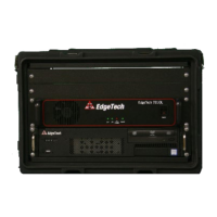
Figure 1-1: 3200 Rack Mount Processor .................................................................................................... 1-5
Figure 1-2: Tiger and Mother Boards inside 3200-XS Topside Processor .................................................. 1-6
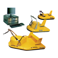
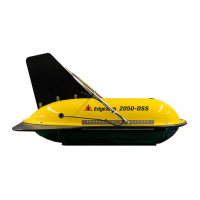
Figure 1-3: SB-424, SB-216S, and SB-512i Tow Vehicles ............................................................................ 1-7
Figure 1-4: 75-Meter Kevlar Reinforced Tow Cable ................................................................................... 1-8
Figure 2-1: Tiger Board Set: Carrier (Front view) – 0006013 ..................................................................... 2-5
Figure 2-2: Tiger Board Set: Carrier (Rear View) – 0006013 ...................................................................... 2-5
Figure 2-3: Tiger Board Set: Acquisition PCB - 0014231 ............................................................................ 2-6
Figure 2-4: Tiger Board Set: SIBU aka Sonar Interface Board – 0011637 .................................................. 2-6
Figure 2-5: SB-216 Towfish Outline Drawing ............................................................................................. 2-9
Figure 2-6: SB-424 Towfish Outline Drawing ........................................................................................... 2-10
Figure 2-7: SB-512i Towfish Outline Drawing .......................................................................................... 2-11
Figure 3-1: Front Panel of 3200-XS Rack Mount Topside .......................................................................... 3-4
Figure 3-2: Topside Rear Panel Controls and Connections ........................................................................ 3-5
Figure 3-3: Reinforced Cable Attached to SB-216S Tow Vehicle ............................................................... 3-8
Figure 3-4: Recommended Method for Dressing and Strain Relieving Tow Cable .................................... 3-8
Figure 3-5: The DISCOVER Sub-Bottom Main Window ............................................................................ 3-10
Figure 3-6: Successful Self-Test ................................................................................................................ 3-11
Figure 3-7: NET: ON .................................................................................................................................. 3-11
Figure 3-8: The Sub-Bottom Control Tab ................................................................................................. 3-11
Figure 3-9: Tap Test .................................................................................................................................. 3-12
Figure 4-1: Retaining Ring and Locking Sleeve Removed .......................................................................... 4-3
Figure 4-2: Male Connector ....................................................................................................................... 4-3
Figure 4-3: Removing the 7/16-Inch Bolts Securing the Teardrop Cover to the Tow Vehicle ................... 4-4
Figure 4-4: Removing the Teardrop Cover ................................................................................................. 4-4
Figure 4-5: Teardrop Cover Removed ........................................................................................................ 4-5
Figure 4-6: Removing 7/16 and ½ Inch Bolts and Nuts .............................................................................. 4-5
 Loading...