3.0: SETUP AND ACTIVATION 3-6
3200-XS SUB-BOTTOM SYSTEM 0004840_REV_E
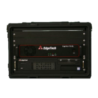
3.5 Rack Mount Deck Unit Connections
Most of the connections to the Rack Mount Deck Unit are made using connectors on the back. These
connectors are shown in F
IGURE 3-1. The trackball and keyboard connections are made using connectors
on the front of the Deck Unit.
The Deck Unit connections are the following:
TRACKBALL: USB on front or rear panel connects to the trackball.
KEYBOARD: USB on front or rear panel connects to the keyboard.
SEA CABLE: 11-Pin female bulkhead connector. Connects to the deck cable.
MONITOR: Mini display port on rear panel connects to the LCD monitor.
COM 1-NAV: DB-9 female connector
RS-232 serial port that connects to the navigation system
COM 3, 5, 6: DB-9 female connectors
RS-232 serial ports that can be used to connect to navigation system
TRIGGER IN: BNC connector
Connects to an external trigger source to trigger the sonar.
TRIGGER OUT: BNC connector. Connects to an external sonar system to trigger it.
ETHERNET: (2) RJ-45 connector
Available for connection to a local area network (LAN) and/or printer
USB: Front Panel:
(2) USB
Rear Panel:
(2) USB2
(2) USB3
(2) USB3.1
AC POWER: CEE-type AC input and output connectors. AC input connector
connects to AC power source, and AC output connectors are available
for powering the LCD monitor and other equipment if required.
 Loading...