8
Electric/Hydraulic TT Thruster 140 - 300
Fig. 1.7.1
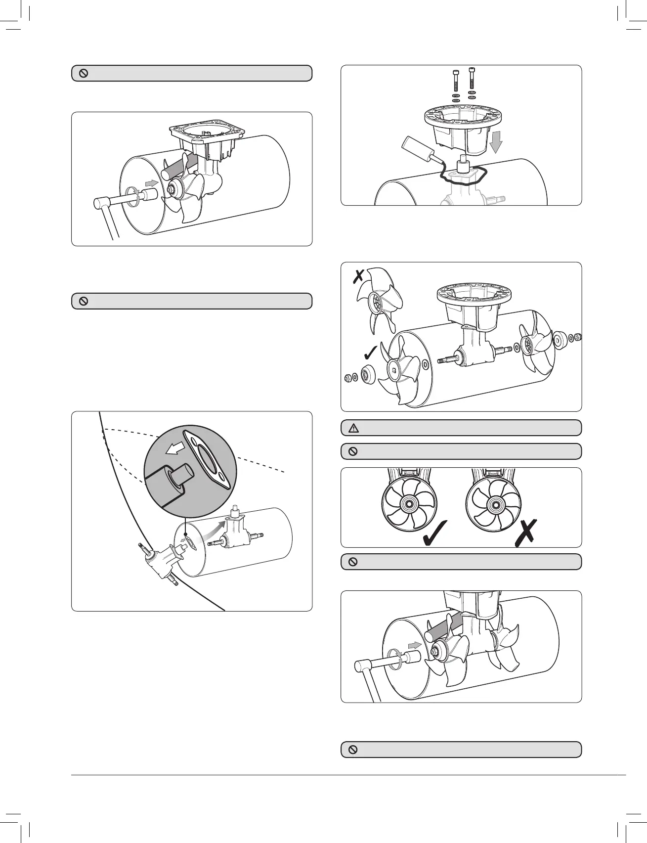
1.7 Installing hub unit and saddle
models 250TT & 300TT
• Place gasket on hub and locate through centre hole. Sealant
can be applied to gasket and fl ange to aid sealing.
NOTE: To achieve the correct position of the
propeller in the tunnel the gasket must be inplace.
Fig. 1.7.2
• Apply zinc chromate paste or marine grease to location bore
and assemble saddle onto hub (SikaFlex® or similar maybe
used to seal saddle in place). Apply Blue Loctite® 243 to bolts
and hand tighten along with supplied washers (Fig 1.7.2).
NOTE: Tighten to full torque within 10 minutes.
NOTE: Tighten each bolt alternately a number of times
to full torque.
• Tighten hub/saddle bolts to 33 Nm (24 lbs.ft) for 250 or 82 Nm
(60.5 lbs.ft) for 300. Check that propeller is centred and free
turning (within 10 minutes of applying Blue Loctite® 243).
Fig. 1.7.2
• Assemble anode kit and propeller in this order:- large washer,
propeller, anode, small washer and nyloc nut onto propeller
shaft. To suit the wiring confi guration supplied fi t the thruster
LH propeller on the port side.
• Tighten propeller nut to 35 Nm (26 lbs.ft), a length of
wood placed between propeller blade and tunnel will stop
movement.
Fig. 1.7.4
• NOTE: Poor exterior tunnel surface could
cause leakage and noise. Apply sealant
to this area as required (Fig 1.7.2).
Fig. 1.6.4
• Tighten propeller nut to 10 Nm (7.4 lbs.ft) for 140 or 15 Nm
(11 lbs.ft) for 185, a length of wood placed between propeller
blade and tunnel will stop movement.
DO NOT overtighten propeller nuts.
• Antifoul bronze hub and propeller if desired.
DO NOT antifoul zinc anode.
DO NOT antifoul zinc anode.
Check the propeller has been assembled correctly (Fig 1.6.1).
• Antifoul bronze hub and propeller if desired.
Fig. 1.7.3
DO NOT allow propeller to touch tunnel.
DO NOT overtighten propeller nuts.
ssue 8.indd 8T1873 Lewmar USA4 Thruster 140 to 300 Issue 8.indd 8 30/04/2007 22:30:5730/04/2007 22:30:57