10
Electric/Hydraulic TT Thruster 140 - 300
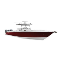
1.11 Installing hydraulic motor unit
model 185TTH to 300TTH
• Place insulator in between saddle and motor fl ange. Line up
key to coupling keyway.
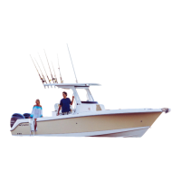
• Remove drive shaft key retaining tie, grease shaft, slide motor
into position and align holes for most suitable installation and
bolt motor assembly to saddle and tighten.
Fig. 1.11.2
Fig. 1.11.1
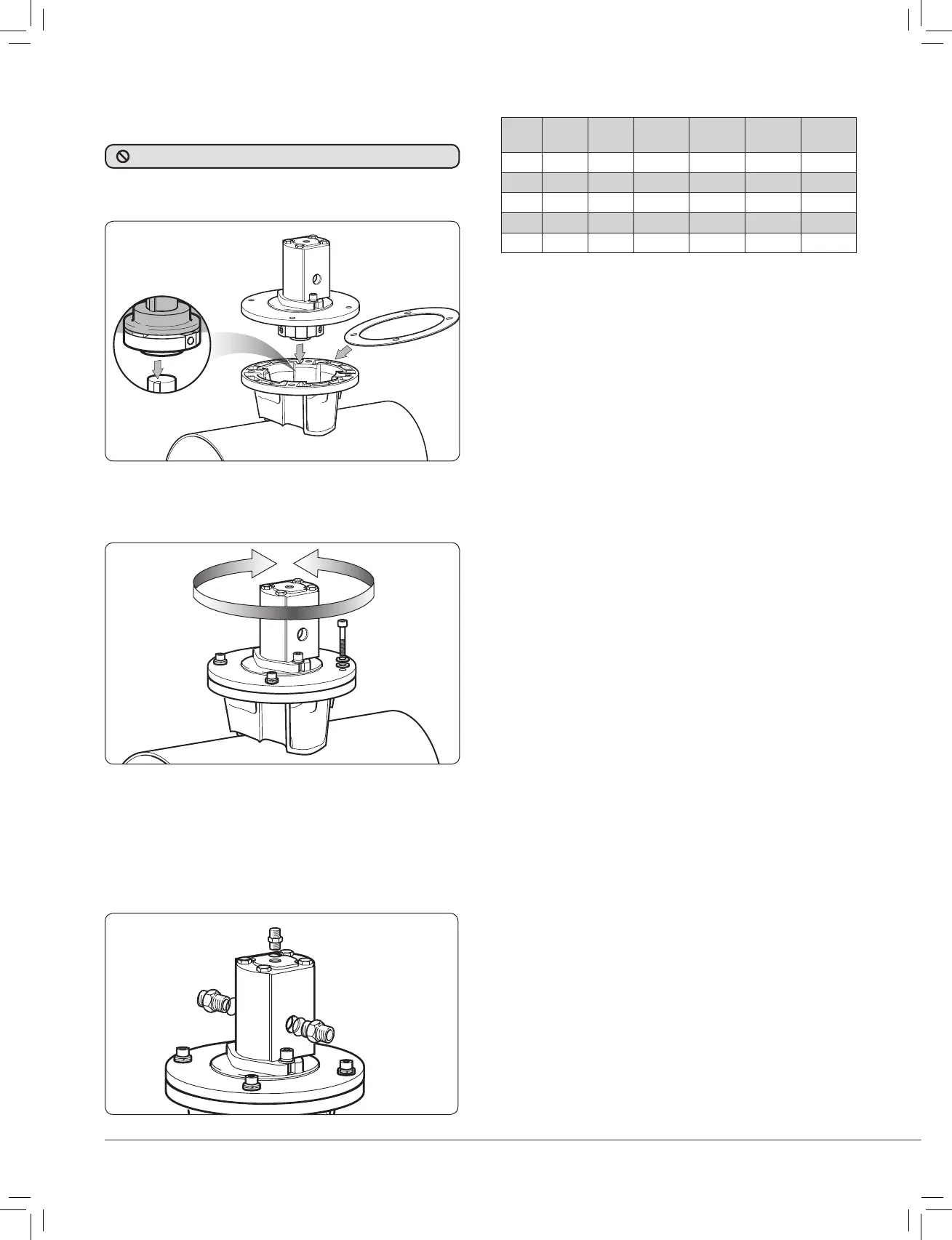
• Motor ports require male/female connectors with correct size
hydraulic sealing washers.
185TT Main ports =
3
/
8
” BSPP.
Main ports =
3
/
4
” BSPP.
Drain ports =
1
/
4
” BSPP.
NOTE: It is advisable to fi t insulated pipe
sections to prevent thruster corrosion.
Fig. 1.11.3
Fig. 1.11.4
Model
Part
No.
Max.
Output
Motor
Disp.
DELTA Flow
Max.
Thrust
185TTH 591820 7 kW 6 cc/rev 210 bar 26 l/min 100 kgf
250TTH 592520 15 kW 26 cc/rev 122 bar 81.5 l/min 200 kgf
250TTH 592521 15 kW 17 cc/rev 190 bar 52.3 l/min 200 kgf
300TTH 593020 22.5 kW 30 cc/rev 182 bar 82.1 l/min 300 kgf
300TTH 593021 22.5 kW 26 cc/rev 210 bar 71.7 l/min 300 kgf
1.12 Final checks - All models
Check list hydraulic
• Check drain line fi tted.
• All fi ttings are tight with seals in place.
• Hydraulic system has been checked and adjusted to correct
pressures and fl ows.
Operation of Hydraulic unit
• Refer to system suppliers instructions.
Check list mechanical
• Check all bolts and nuts are tight.
• Check the propeller/s are correctly installed and the nuts
tightened.
• Check the motor control box cover is in place.
• Check the propeller/s can be turned - before working on unit
check battery switch is off or remove the fuse.
NOTE: Saddle and motor are
fi rmly seated on the tube.
Coupling is factory fi tted. DO NOT remove.