9
Electric/Hydraulic TT Thruster 140 - 300
GB
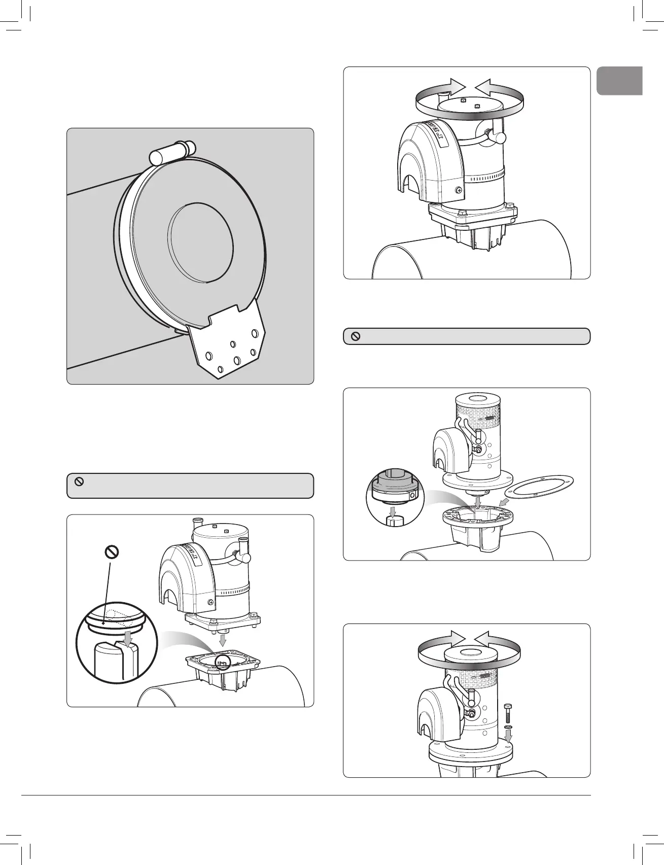
1.8 Electric motor unit support
• If the electric motor is installed more than 30° from the vertical
it MUST be supported and secured to the support with a strap
(not supplied) around the main motor unit.
Fig. 1.8.1
1.10 Installing electric motor
unit model 250TT & 300TT
• Place insulator in between saddle and motor fl ange. Line up
key to coupling keyway.
• Remove drive shaft key retaining tie, grease shaft, slide motor
into position and align holes for most suitable installation and
bolt motor assembly to saddle applying Blue Loctite® 243 to
bolts.
Fig. 1.10.2
Fig. 1.10.1
1.9 Installing electric motor unit
model 140TT & 185TT
• NOTE: Illustrations based on 140TT saddle.
• Align motor drive pin inline with slot in shaft. Apply grease to
hub shaft.
Fig. 1.9.1
• Slide motor into position and align holes for most suitable
installation.
• Bolt motor assembly to saddle and tighten bolts to 20 Nm
(15 lbs.ft) for 140 or 35 Nm (25.8 lbs.ft) for 185. Apply Blue
Loctite® 243 to all bolts.
Fig. 1.9.2
DO NOT REMOVE the drive pin plastic retainer tie on the motor
drive shaft.
Coupling is factory fi tted. DO NOT remove.