14
Electric/Hydraulic TT Thruster 140 - 300
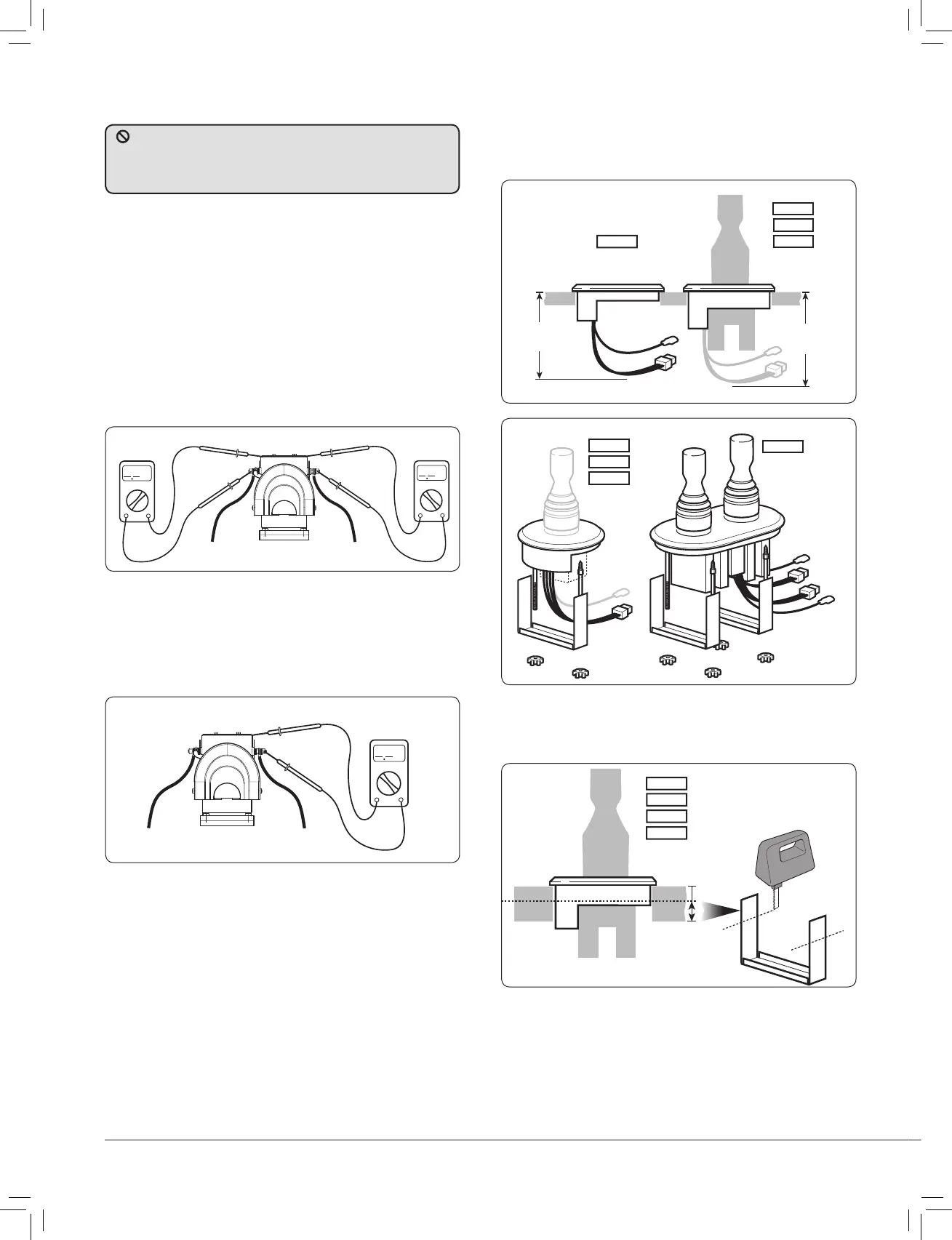
2.8 Installing control panel - all models
• A 63.5 mm (2
1
/
2
”) hole saw is required. Ensure there is
suffi cient depth for the control panel and access for the switch
leads and plug (see saw template).
Fig. 2.8.1
• The panel has an integral seal and can be clamped from the
rear or with the bezel from the top. Trim clamp depending on
panel thickness.
Fig. 2.8.2
589002
589003
589004
589001
589002
589003
589004
2.7 Electrolytic test
• Test 1. Fig.2.7.1
With the negative not connected and the positive cable
connected but with battery switch off or fuse removed. Use a
continuity tester to check for a connection between the –VE
stud and motor body and also between +VE stud and motor
body. In both cases the meter should give no indication of an
electrical connection.
If a connection is measured between the +VE stud and the
motor body, check installation for cables or wires touching
the assembly or for damage to assembly.
If a connection is measured between the –VE stud and the
motor body, remove any bonding straps attached to the
assembly and check as before.
Fig. 2.7.1
Fig. 2.7.2
• Test 2. Fig 2.7.2
With the battery applied: Use a voltmeter to test the
voltage between the –VE motor stud and the thruster
motor body. If the supply voltage (12 V/24 V)
is measured, disconnect power immediately and inspect the
assembly for faulty installation or damage.
To prevent electrolytic corrosion or faults, the thruster motor
body and assembly MUST remain isolated from any power supply
or grounds. The installer can check for this using a multimeter in
the following ways.
Fig. 2.8.3
589001
589002
589003
589004
589001