12
Electric/Hydraulic TT Thruster 140 - 300
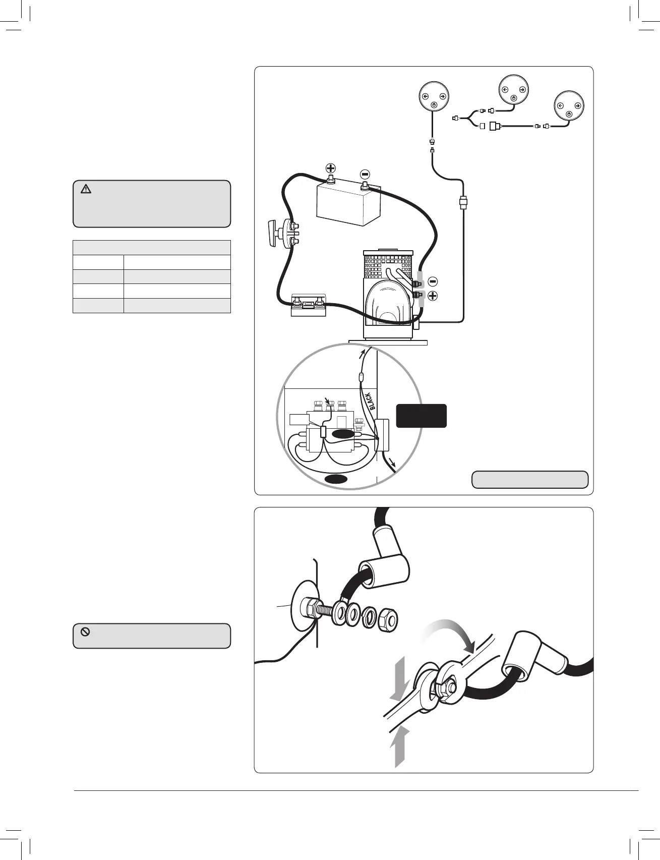
2.3 Typical electrical layout
models 250TT & 300TT
•. If the thruster operates in an opposite
direction to the control panel, swap the
white and violet wire connections on
the contactor coils.
NOTE: Automatic switch (if
fi tted).Main power is switched
on when panel is switched on.
MOTOR
FUSE
BATTERY
BLACK
BOX
CONTROL
BOX
+VE
–VE
BATTERY SWITCH
OR
AUTOMATIC BATTERY
SWITCH 589034
(If fitted)
RED
VIOLET
WHITE
RED
THERMAL
SWITCH
CONTROL BOX
COVER
REMOVED
TO
CONTROLS
BLACK
BOX
BLACK
(POSITIVE) STUD*
* Solenoid
appearance may differ.
Fuse 5 A
5x20 mm
Fig. 2.3.1
Fig. 2.41
2.4 Electric motor
terminal connections
• Terminals must be correctly clamped
to motor studs. Use a pair of spanners
- the one nearest motor to stop rotation
of the stud.
• Spanner sizes are 13 mm for 140TT and
17 mm for 185TT - 300TT. Tighten the
bolts to 20 Nm (15 lbs.ft).
Loom Wiring
Red
+VE
Blue
Thrust port switch
Grey
Thrust starboard switch
Black
–VE
Negative Switching
NOTE: For dual thruster
controls see stern thruster
manual included in sternkit
or on www.lewmar.com
It is vital that the positive battery
lead is connected to the positive motor
terminal or damage to the electronics
will occur.
DO NOT overtighten electric motor
terminal nuts.