ES-10B 4 Terminal Single Phase Residential Electricity
Meter - Product Guide
Copyright © 2019 EDMI Europe Ltd. All rights reserved
Version / Status: 1.1
Public
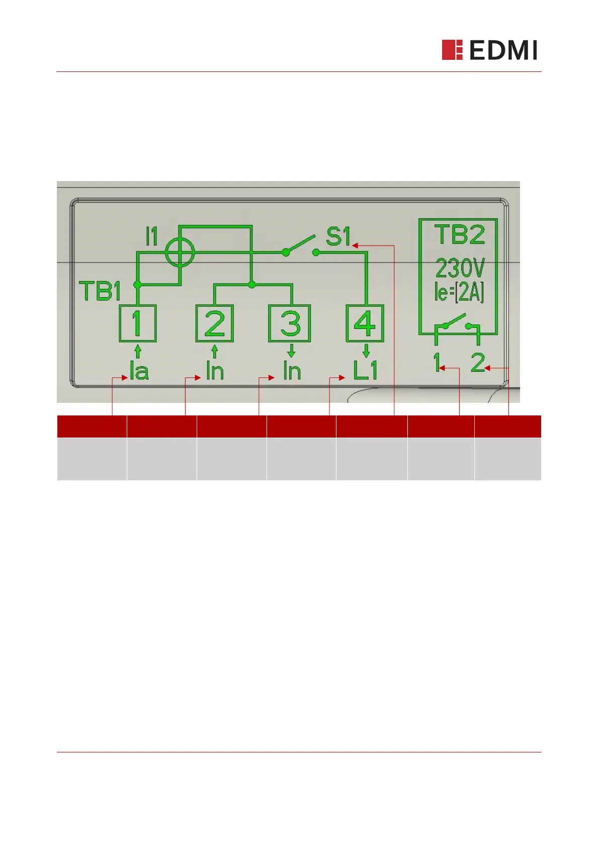
The diagram below is printed on the underside of the terminal cover and is provided for reference
to ensure the meter is connected correctly.
Figure 7-4: Terminal Connections
The following diagram is embossed on the underside of the meter terminal cover. The following is
highlighted here in green for clarity.
Main circuit
load
100A max
7.4 Current and Voltage
The meter’s voltage and current ratings are specified in section 18
7.5 Auxiliary Load Control Switch (ALCS)
The ES-10B is fitted as standard with a 230VAC 2A ALCS relay connection. This output should not
be used as a pulsing output for transmitting energy pulses, as the output contacts are subject to
contact bounce and are not rated for continuous switching. The relay can be turned on indefinitely,
and is primarily designed to switch small loads or drive an external contactor.
For the locations of the outputs see Figure 7-3. A basic specification and connection diagram is
shown underneath the terminal cover as shown in Figure 7-4.