Chapter 1: Introduction
2 P/N 3102309-EN • REV 001 • ISS 18JUL19
System overview
The EST4 life safety system can operate as a stand-alone control unit or as part of an EST4 life safety network.
The EST4 user interface includes indicators and operator controls that allow you to respond quickly in emergency
situations. The user interface gives you the ability to view message details and system reports, and to enable and
disable devices and groups. With the correct fire privilege PIN, you can activate and restore sensitivity settings,
test system devices, and perform other tasks.
EST4 LCD user interface
An EST4 system uses LCD display modules to provide the user interface for the fire alarm control unit.
• The 4-LCD and 4-3LCD modules are main LCD display modules that include operator command controls,
LED indicators, and an LCD screen.
• The 4-LCDAUDTEL Audio and Firefighter Telephone Control LCD Display Module includes an operator LCD
screen.
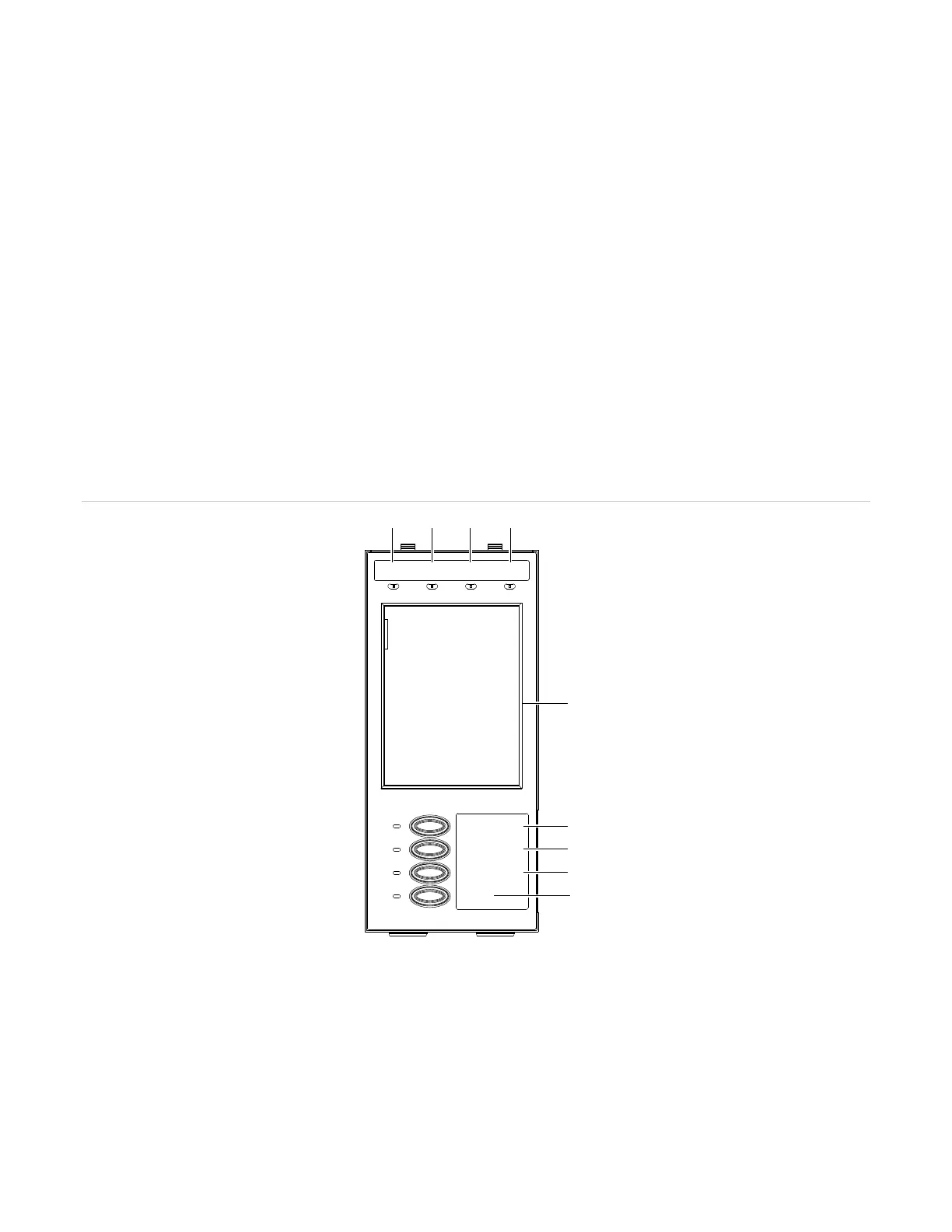
Figure 1: LCD user interface (4-LCD shown)
Command controls and indicators
The 4-LCD and 4-3LCD user interface command controls and indicators are shown in Figure 1 above. See
Table 1 on page 3 for a description of each control and indicator.
(1)
(2) (3) (4)
ALARM CPU FAILTROUBLE POWER ON
PANEL SILENCE
FIRE DRILL
ALARM SILENCE
RESET
(5)
(6)
(7)
(8)
(9)