Appendix A: System addressing
50 P/N 3102309-EN • REV 001 • ISS 18JUL19
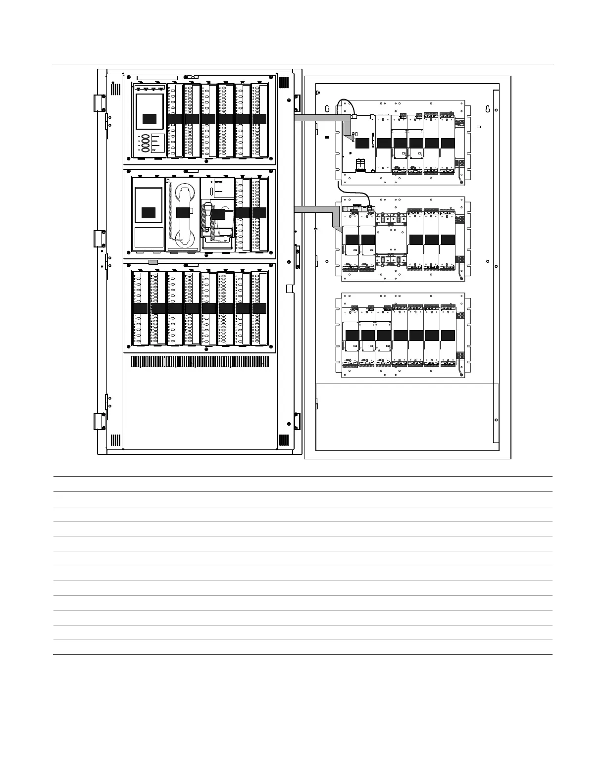
Figure 14: Logical addressing for control unit with multiple nodes (4-CAB21DL inner door/4-CAB21B backbox shown)
Table 12: Logical addressing for a control unit with multiple nodes
Logical address
Operator layer modules on the inner door frame assembly
-LCD NNN064(065)
-display modules NNN066 to NNN071
-LCDANN NNN064(065) [1]
-FT NNN066(067) [2][4]
-MIC NNN068(069) [3]
-display modules NNN070 to NNN079
-CHAS7 chassis
-CPU NNN000
NNN001 to NNN007 [4]
NNN010 to NNN019
[1] Logical addressing restarts with NNN064 when the 4-LCDx is connected to the CPU node module.
[2] The logical address for a 4-FT firefighter telephone is always NNN066.
[3] The logical address for a 4-MIC paging microphone is always NNN068.
[4] Local rail modules cannot be installed on the 3-CHAS rail behind a 4-FT firefighter telephone.
064
064
072
073
066
066
074
067
075
068
076
069
077
070
070
078
071
071
079
000
001
015
006
013
002
016
007
014
003
010
017
004
011
018
005
012
019
068