Check the integrity and continuity of the wir-
ing between connector J26 (on board AP1)
and connector F1/F4 (on board A2), and re-
place it or repair if necessary.
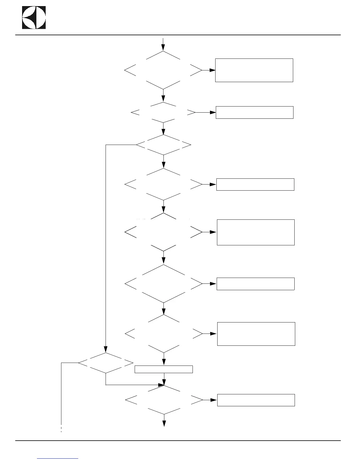
Check the correct power supply
230V (-15%; +10%) on MEC
board A2 in connectors F1/F4
(see Layout 6 - page 69 - con-
tacts 1 and 2).
NO
YES
Sostituire la scheda MEC A2.
YES
NO
NO
YES
Replace MEC board A2.
Replace board AP1.
Verificare la corretta alimnetazi-
one 230V (-15%; +10) sulla
scheda AP4 (zona prelavaggio
44”) o sulla scheda AP5 (zona
prelavaggio 22”) nel connettore
J25 tra i contatti 1 e 2.
NO
YES
NO
YES
Replace boards AP4/AP5.
NO
Check the wiring, the through-wall fittings
(XC_4 - Wash+Rinse zone, (XC_35 - Pre-
wash zone 44" and (XC_44 - Prewash zone
22") and the connectors, and repair/replace if
necessary.
NO
YES
Return to the wash zone.
NO
YES
Replace boards AP1.
Continued on next page.
YES
Check the correct power supply
230V (-15%; +10%) on board
AP1 in connector J25 (contacts
1 and 2).
Check the correct power supply
230V (-15%; +10%) on board MEC
A6 (prewash zone) in connector
F1/F4 (see Layout 5 - page 68 -
contacts 1 and 2).
Check the correct power supply
230V (-15%; +10%) on board
AP4 (prewash zone 44") or on
board AP5 (prewash zone 22")
in connector J25 (contacts 1 and
2).
Check the correct power supply
230V (-15%; +10%) on board
AP4/AP5 in connector J26 (con-
tacts 1 and 2).
Check the integrity and continuity of the wir-
ing between connector J26 (on board AP4/
AP5) and connector F1/F4 (on board A6),
and replace/repair if necessary.
Check the correct power supply
230V (-15%; +10%) on board
AP1 in connector J24 (contacts
1 and 2).
If the alarm is only CoM Err2
and there is no error CoM
Err3 or CoM Err4 in progress.
YES
Is the Prewash mod-
ule installed?
Is the DT module in-
stalled?
NO
YES
NO