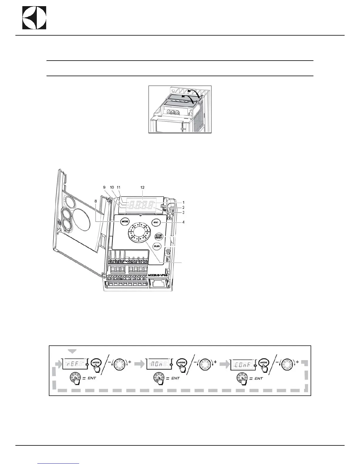
When replacing the inverter remove the two protection labels on the top of the same, as indicated
below (the protection rating becomes IP20).
D2.1 INVERTER PROGRAMMING
D2.1.1 FUNCTIONS OF THE DISPLAY AND KEYS
1. Value LED (see note a and b)
2. Charge LED
3. Unit LED (see note c)
4. ESC button: Exits a menu or parameter, or aborts
the displayed value to return to the previous value
in the memory. In LOCAL configuration, 2 s press
on ESC button switches between the control/pro-
gramming modes.
5. Jog dial
- Acts as a potentiometer in LOCAL configuration
and in REMOTE configuration if the function is
configured.
- For navigation when turned clockwise or counter-
clockwise and selection / validation when
pushed.
6. CONFIGURATION mode LED (see note b).
7. MONITORING mode LED.
8. REFERENCE mode LED.
9. Four "7-segment" displays.
Note: In LOCAL configuration, the three Leds 9, 10,
11 are blinking simultaneously in programming mode
and are working as a Led chaser in control mode.
(a) If illuminated, indicates that a value is displayed, for exam-
ple,
is displayed for “0.5”.
(b) When changing a value the Configuration mode LED and
the value LED are on steady.
(c) If illuminated, indicates that a unit is displayed, for example,
AMP is displayed for "Amps".