22
* If inputs AI3 and AI4 are not set as DI, parameters CF25 and CF26 parameters must be set to 0. Failure to observe
this rule may result in malfunctions.
** If inputs AI3 and AI4 are set as DI, parameters CF14 and CF15 parameters must be set to 0.
*** The unit of measurement (U.M.) is selected based on parameters CF02 and CF03 and parameters UI22 (C°/F°) and
UI23 (Bar/Psi).
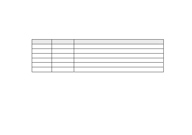
Inputs AI3 and AI4 are configurable as indicated in the following table (CF02 ... CF03):
Value Type Description
0 None Probe not configured
1 DI Probe configured as potential-free contact digital input
2 NTC NTC probe range -50.0°C ÷ 99.9 °C
3 4-20mA Analogue input 4-20 mA
4 0-10V Analogue input 0-10 V
5 0-5V Analogue input 0-5 V
Notes:
If an input is configured as NTC, the corresponding parameters are always displayed with the “thermometer” icon.
(UI22=0/1; U.M.= C°/F°)
If an input is configured as 4-20mA, 0-10V or 0-5V, the corresponding parameters are displayed with U.M. =Bar if
UI23=0 with U.M.=Psi if UI23=1.
Parameters CF04 ÷ CF07
Indicate the reading scale analogue limit values for inputs configured as 4-20mA, 0-10V, 0-5V. (Inputs 3 and 4 only)
If the input is not configured as input 4-20mA, 0-10V, 0-5V, the end of scale parameters lose meaning.