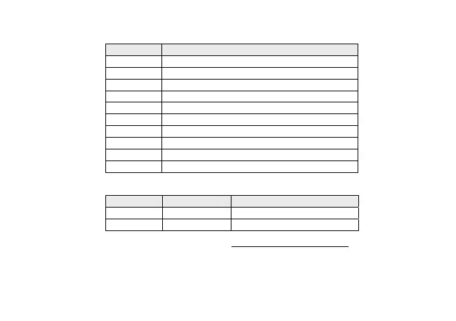
24
Parameters CF16 ÷ CF20 and CF23 ÷ CF26
Indicate the logical meaning of the analogue inputs.
Value Description
± 0 Input disabled
± 1 Outlet pressure switch
± 2 Inlet pressure switch
± 3…± 6 Block compressor 1…4
± 7 Continuous compressor shut-down (inverter)
± 8…± 11 Fan 1..4 thermal switch
± 12 Continuous fan/shared fans thermal switch
± 13 Remote On/Off
± 14 General alarm
± 15 … ± 21 Not used
Polarity is defined below:
Value Type Description
+ Positive Active when contact closed
- Negative Active when contact open
If multiple inputs are configured with the same value, only the input with the highest index is active (an OR logic is
not executed)