2. MOTOR (Fig. 9)
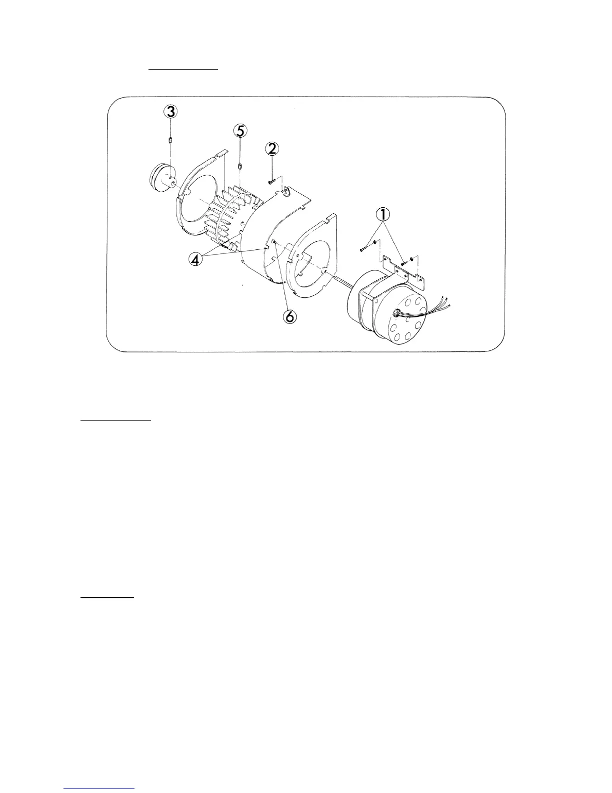
Fig. 9
DISASSEMBLY
1. Remove Transformer. (Refer to page 8)
2. Take out AMP assy. (Refer to page 15)
3. Take out attaching screws (Fig.9-1,x4) and (Fig.9-2), and remove Motor unit assy.
4. Loosen attaching screws (Fig.9-3,x2) and pullout Pulley unit (just Pulley 50 Hz or with Pulley
60 Hz).
5. Straighten out the latches (Fig.9-4,x8) of Fan casing 3 and remove Fan casing 2 and Fan casing
3.
6. Loosen attaching screws (Fig.9-5,x2) and pullout Fan.
7. Take out attaching screws (Fig.9-6,x2) and remove Fan casing 1.
ASSEMBLY
1. As to the assembling, follow the reverse way of the above steps.
2. Fan should not be interrupted by Fan casing 1,2,3.
- 9 -


 To Next Page