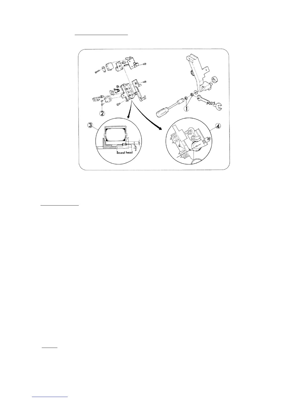
4. SOUND HEAD (Fig. 18)
Fig. 18
REPLACEMENT
1. Remove Loop setter holder. (Refer to page 16)
2. Take out attaching nuts (Fig.18-1,x2) in turn and remove Pad roller lever. To do this, special
tool No. P025 had better to be used.
3. Take out attaching screws (Fig.18-a,x2), and replace Sound head.
4. Attach Sound head temporarily so that the top of Sound head could position a little (h/3) higher
from the surface of Head film guide as illustrated (Fig.18-3) also Sound head and Head presser
roller could line up in a straight line as illustrated (Fig.18-4).
5. Attach Pad roller lever and tighten attaching nuts (Fig.18-1,x2) in turn.
6. Pass the magnetic pre-recorded test film (5000 Hz).
7. Connect both the resistor (8 ohms, 10W) and the voltage meter (AC 10V max.) parallel to the
output terminals of the amplifier (Extension speaker cord terminal).
8. Run the projector, move Sound head gradually to search the position where the output voltage
is maximized, under Volume control knob positioned somewhat below max.
9. Secure attaching nuts (Fig.18-1,x2) and attaching (Fig.18-2,x2) by screw-tight.
10. Attach Loop setter holder.
NOTE: P025 .. Pad roller lever spanner (Offer price US$1.00, FOB JAPAN)
- 18 -
 Loading...