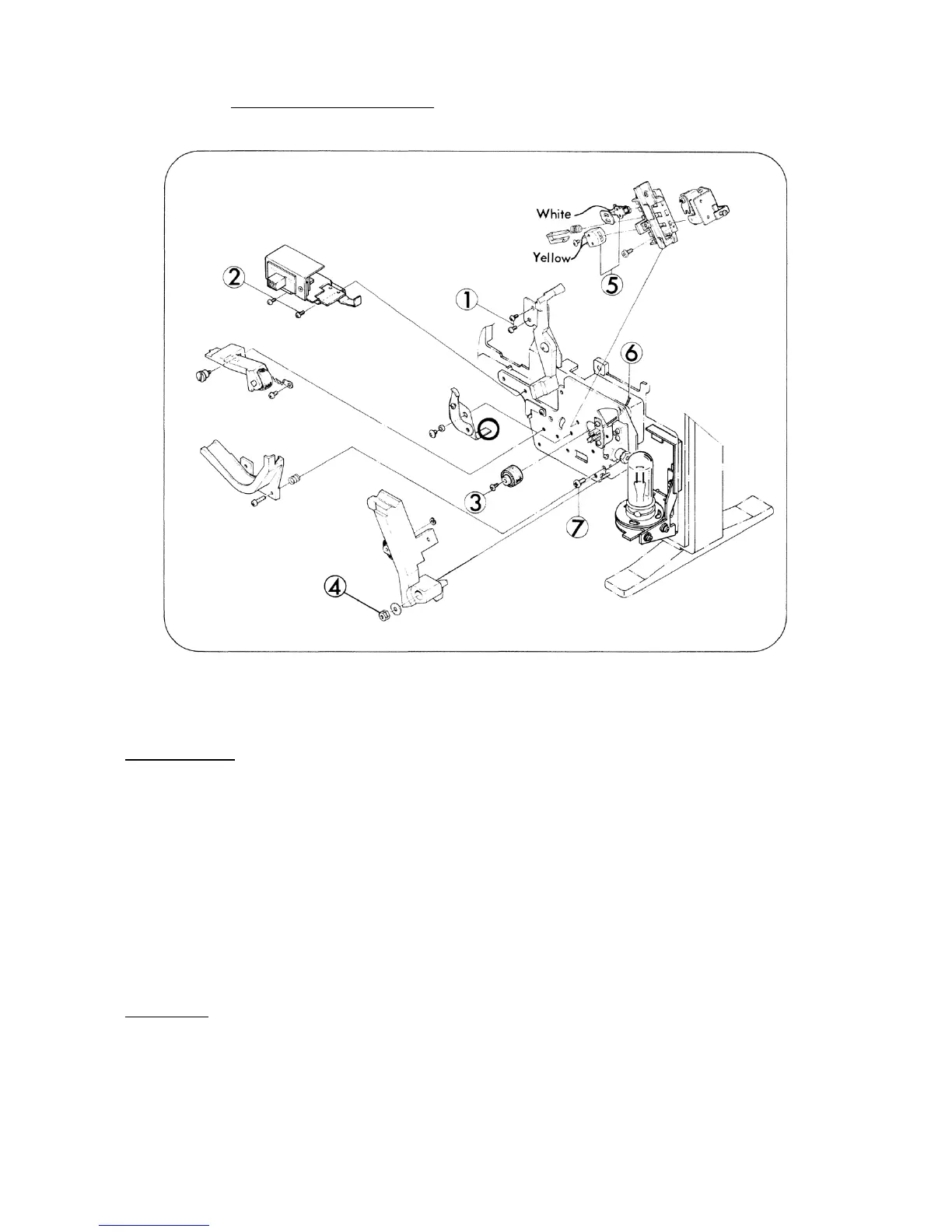
2. HEAD BASE PLATE (Fig. 16)
Fig. 16
DISASSEMBLY
1. Take out attaching screws (Fig.16-1,x2) and remove Loop setter holder.
2. Take out attaching screws (Fig.16-2,x2) and remove M-O changing holder. Optical guide and
Optical guide spring come off this time.
3. Take out attaching screw (Fig.16-3) and remove Sound drum.
4. Take out attaching nuts (Fig.16-4,x2) in turn and remove Pad roller lever.
5. Unsolder the end of the wires (Fig.16-5,x2) connected to Sound head and Erasing head.
6. Disconnect the connecting pin of the wire (Fig.16-6) on AMP assy side. (Refer to page 15)
7. Take out attaching screws (Fig.16-7) and remove Head base plate assy.
ASSEMBLY
1. As to the assembling, follow the reverse way of the above steps.
2. Attach Head base plate assy so that Reverse lever (1) and Reverse lever could join to cooperate.
- 16 -
 Loading...