E. SOUND
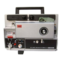
1. AMPLIFIER (Fig. 15)
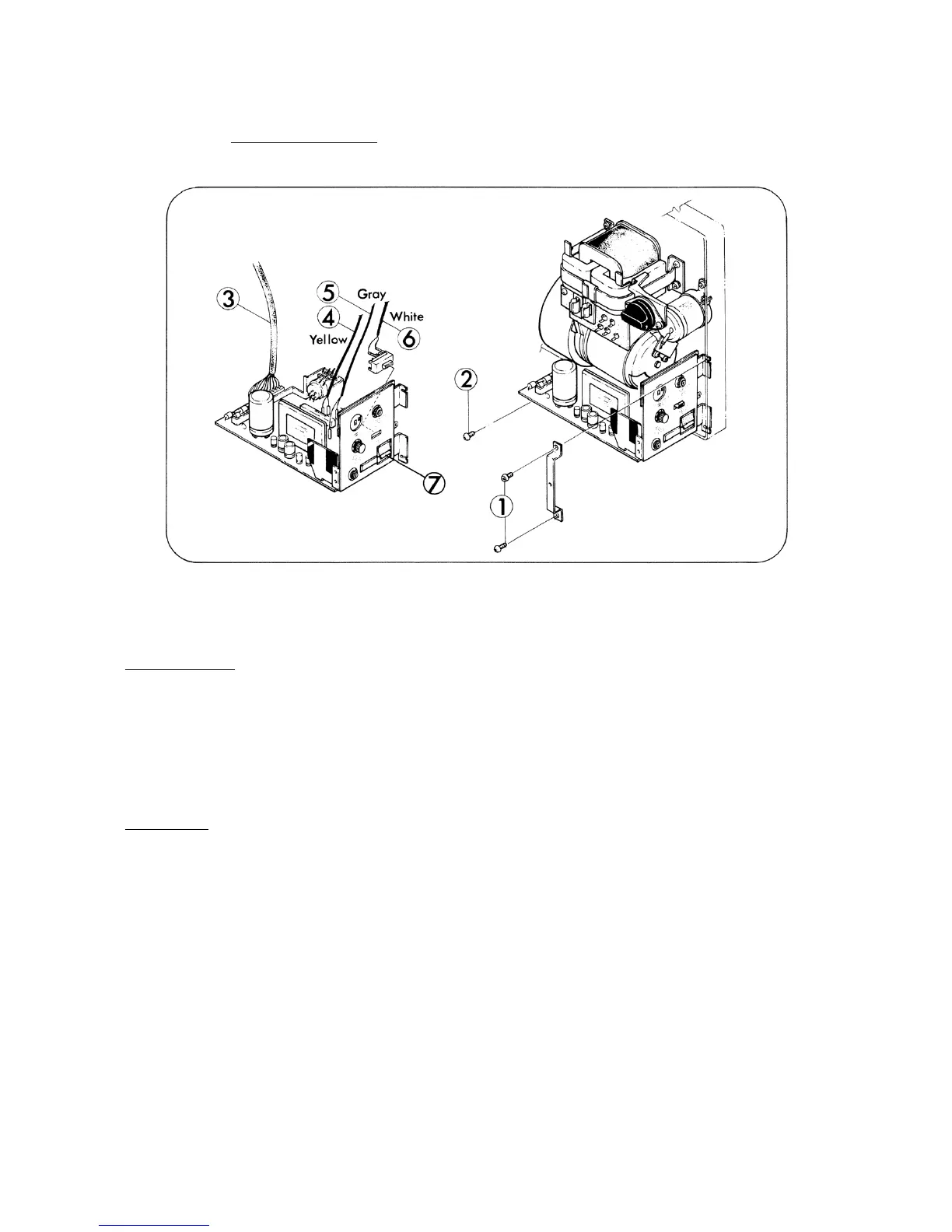
Fig. 15
DISASSEMBLY
1. Pull out Volume control knob and Tone control knob.
2. Take out attaching screws (Fig.15-I,x2) and remove AMP decoration plate.
3. Take out attaching screw (Fig.15-2) and pull out AMP assy.
4. Disconnect the connector pin of the wires (Fig.15-3,4,5,6) and remove AMP assy.
ASSEMBLY
1. Connect the connector pin of the wires (Fig.15-3,4,5,6) to AMP assy.
2. Position Motor switch knob F and attach AMP assy to Base frame so that Switch cam and
Recording knob assy could cooperate.
3. Attach AMP decoration plate and tighten attaching screw (Fig.15-1,x2) (Fig.15-2) temporarily.
4. Fit AMP assy so that a click of Micro switch could not be made while Motor switch positioned S,
but a click of Micro switch could be made while Motorswitch positioned F besides being
Recording knob pushed.
5. Attach Volume control knob and Tone control knob.
- 15 -
 Loading...