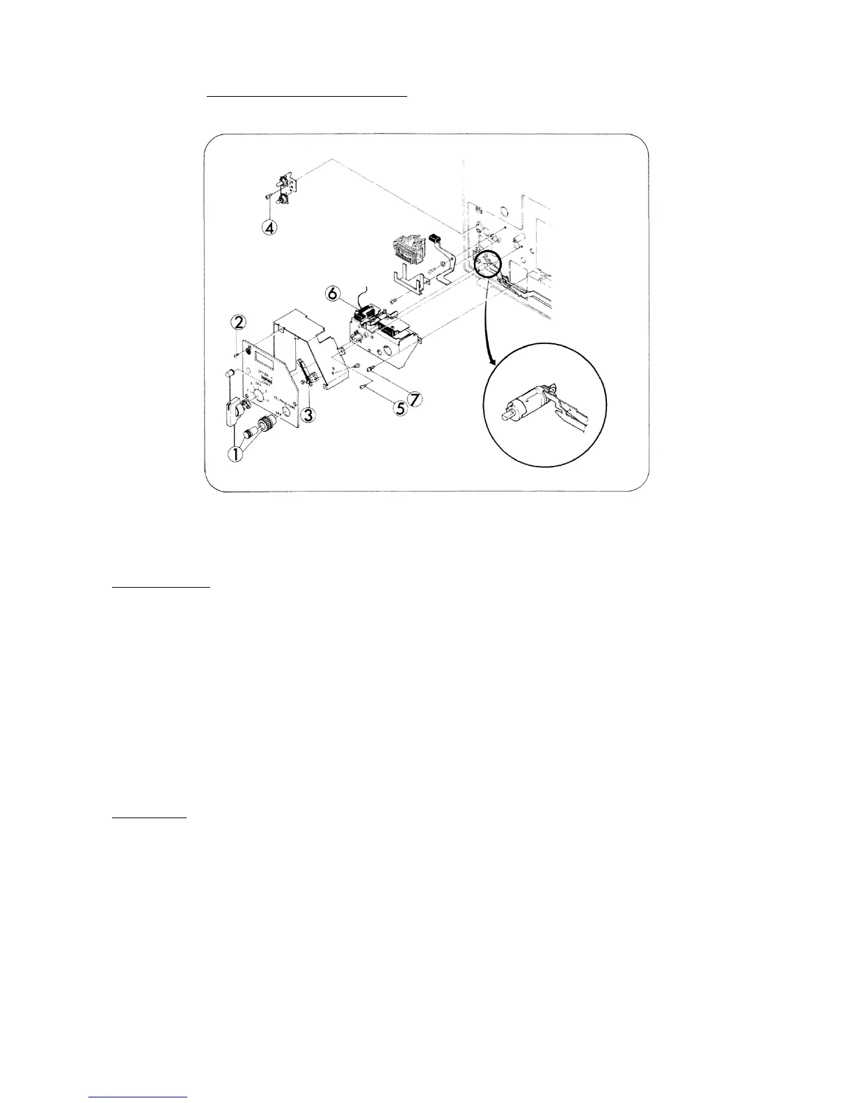
5. SWITCH MECHANISM (Fig. 12)
Fig. 12
DISASSEMBLY
1. Pull out knobs (Fig.12-1,x3) such as Motor switch, Volume control and Tone control knobs. To do
this, Motor switch knob should be positioned F.
2. Take out attaching screws (Fig.12-2,x3) and remove Switch panel.
3. Unsolder the end of the wires (x2) connected to Release switch (Fig.12-3).
4. Take out attaching screw (Fig.12-4) and remove Pilot lamp holder.
5. Take out attaching screw (Fig.12-5) and remove Switch cover.
6. Unsolder the end of the wire connected to Micro switch V-2A (Fig.12-6).
7. Take out attaching screws (Fig.12-7,x3) and pull out Switch assy.
ASSEMBLY
1. Pull out AMP assy. (Refer to page 15)
2. Attach Switch assy to Base frame. To do this, first, join Switch cam and both Reverse lever and
Clutch lever (3) as indicated in Fig. 12, and tighten attaching screws (Fig.12-7,x3).
3. Attach AMP assy.
4. To complete the rest, follow the reverse way of the above steps. (Disassembly: 6, 5, 4, 3, 2, 1)
- 12 -
 Loading...