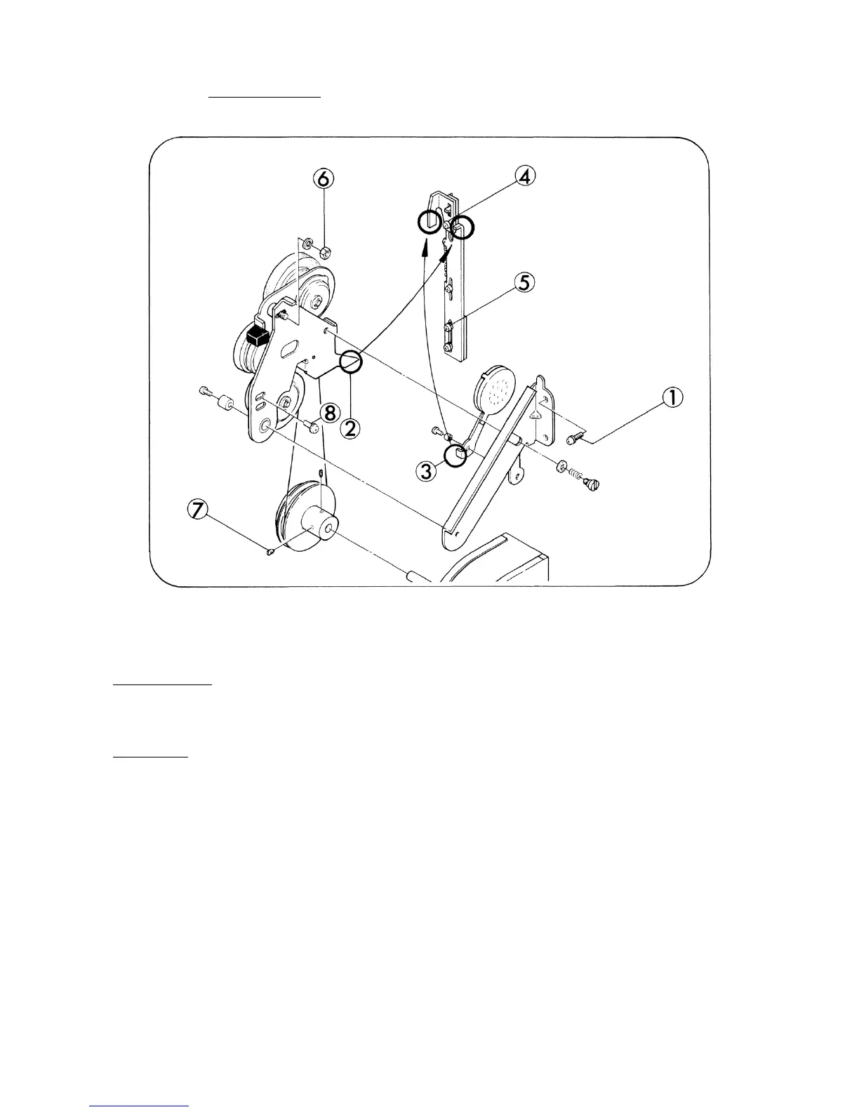
3. CLUTCH (Fig. 10)
Fig. 10
DISASSEMBLY
1. Take out attaching screws (Fig.l0-l,x2) and remove Clutch unit assy and Drive belt.
ASSEMBLY
1. Hang Drive belt on Clutch unit assy and push against Base frame.
2. To do this, first join Clutch lever (1) assy (Fig.10-2) and Clutch link (1) either Safety shutter
(Fig.l0-3) and Safety shutter presser as indicated in Fig. 10 to achieve respectable movement,
and tighten attaching screws (Fig.l0-l,x2).
3. If Safety shutter could not keep off from the optical axis of the screen during Motor switch knob
positioned F or R, loosen attaching screw (Fig. 10-4) and adjust the position of Safety shutter
presser.
4. If Clutch unit assy could not convey the rotation of Motor assy during 18 f/s or 24 f/s projection,
loosen attaching screws (Fig.l0-5) or attaching nut (Fig.l0-6) and adjust the position of Clutch
link adjuster and Clutch lever (2) assy.
- 10 -
 Loading...