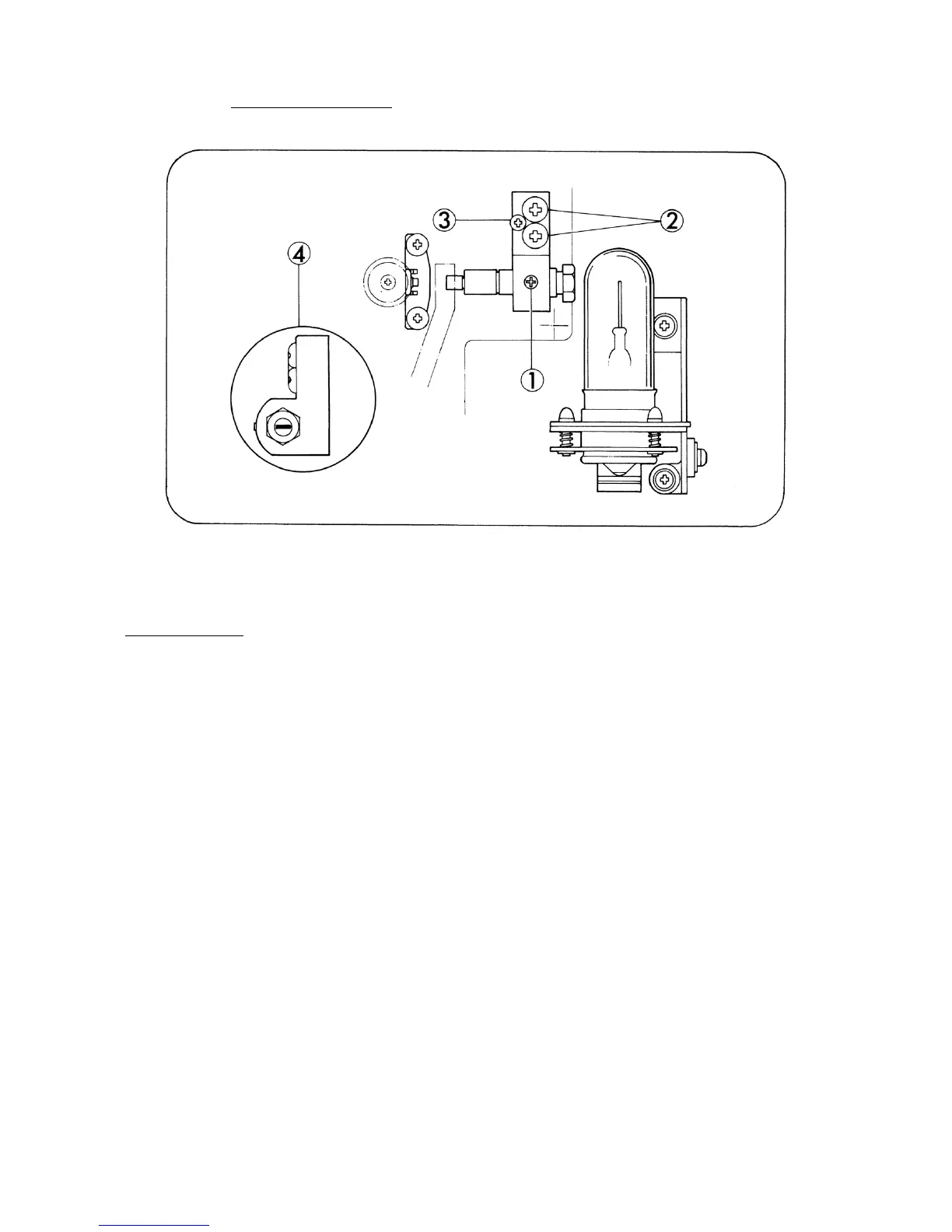
3. SOUND LENS (Fig. 17)
Fig 17.
REPLACEMENT
1. Remove Exciter lamp.
2. Remove Pad roller lever. (Refer to page 18)
3. Loosen attaching screw (Fig.17-1) and pull out Sound lens assy. Insert replacement Sound lens
assy of which window to be parallel to the optical axis as illustrated (Fig.17-4).
4. Install Exciter lamp.
5. Light Exciter lamp and first loosen attaching screws (Fig.17-2,x2) slightly and either tighten or
loosen attaching screw (Fig.17-3) to adjust the slit image through Sound lens can be screened in
the center of Silicon photo diode.
6. Attach Pad roller lever.
7. Pass the optical focusing test film (4000 Hz).
8. Connect both the resistor (8 ohms, 10W) and the voltage meter (AC 10V max.) parallel to the
output terminals of the amplifier (Extension speaker cord terminal).
9. Run the projector, move Sound lens back and forth to search the position where the output
voltage is maximized, under Volume control knob positioned somewhat below max.
10. Secure all the attaching screws by screw-tight.
- 17 -
 Loading...