D. MACHINE FRAME
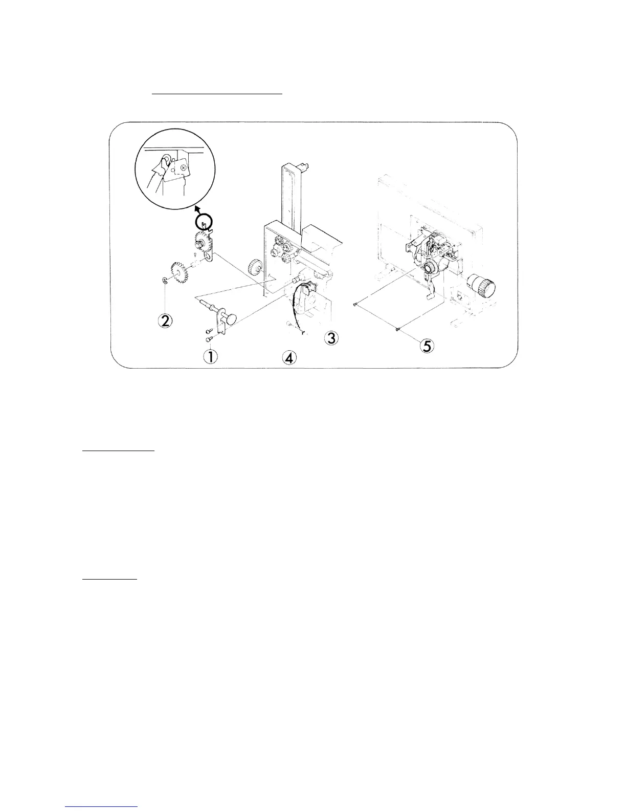
1. MACHINE FRAME· (Fig. 13)
Fig. 13
DISASSEMBLY
1. Take out attaching screws (Fig.13-l,x2) and remove Threading knob holder.
2. Take out attaching E-ring (Fig.13-2) and remove Changing gear as well as Sprocket shaft pin,
then remove Changing holder from Sprocket shaft (1).
3. Unsolder the end of the wires (x2) connected to Solenoid assy (Fig.13-3) and loosen attaching
screw (Fig.13-4), then remove the wires (x2) from cord supporter.
4. Take out attaching screws (Fig.13-5,x3) and pullout Machine frame assy.
ASSEMBLY
1. Attach Machine frame assy of which Loop former should be released and tighten attaching
screws (Fig.13-5,x3) strong enough.
2. Solder the end of the wires (x2) to Solenoid assy (Fig.13-3) and hold the wires by Cord
supporter, then tighten attaching screw (Fig.13-4).
3. Insert Changing holder to Sprocket shaft (1). To do this, join the “U” shaped hollow to Changing
plate lock (1) as indicated in Fig.13.
4. Attach Sprocket shaft pin and Changing gear, and clasp attaching E-ring (Fig. 13-2).
5. Attach the Threading knob holder with attaching screws (Fig.13-1,x2) so that pulled-out
Threading knob could complete the single frame feed.
- 13 -


 To Next Page