Elna International Corps. SA 6004 Service manual
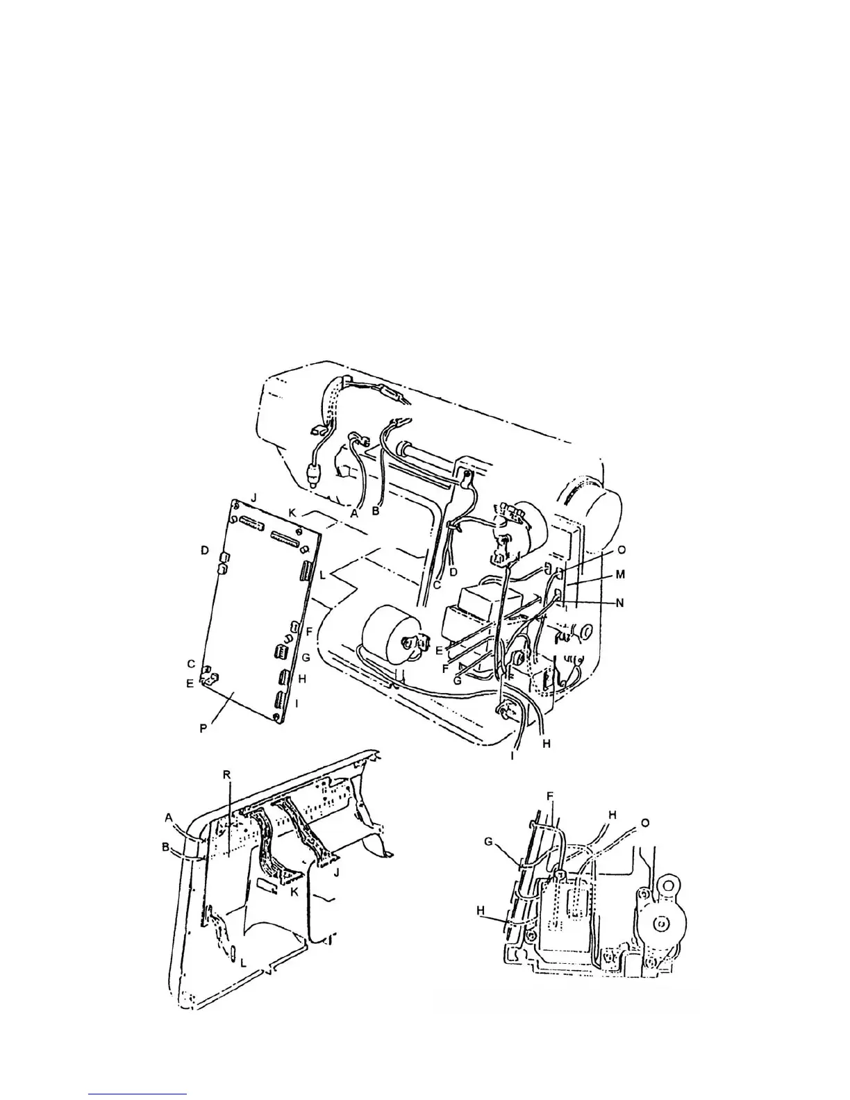
WIRING DIAGRAM
The connectors oft the electrical components should be connected to the respective positions
shown in the figure below.
A = Thread tension switch I = Stepp motor (feed)
B = BH sensor J = Connector circuit R
C = Lamp socket K = Connector circuit R
D = Upper shaft sensor L = Connector circuit R
E = Circuit board C M = Cicuit board C
F = Machine socket (secondary circuit) N = Transformer secondary cord
G = DC motor (Main Motor) 0 = Machine socket primary cord
H = Stepp motor (zigzag) P = Circuit board A
R = Circuit board K
Page 26