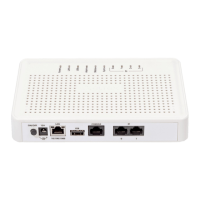
SMG digital gateway 11
A controller featuring:
a controlling CPU,
flash memory of 64 MB,
512 MB RAM;
М4Е1 submodule of E1 streams;
SM-VP-M200 IP submodule for SMG-2;
SM-VP-M300 IP submodule for SMG-4;
a phase-lock-loop (PLL) frequency control system.
See the SMG functional chart in Fig. 4.
Fig. 1.5—SMG Functional Chart
In the TDM-IP direction, a signal coming to E1 streams is transferred to VoIP submodule audio codecs (a
line of 128 TDM channels) via the intrasystem backbone to be encoded using one of the selected standards and
further transferred as digital packets to the central processing unit. In the IP-TDM direction, digital packets are
transferred to the VoIP submodule to be decoded and further transferred to E1 streams via the intrasystem
backbone.
External 2 Mbps E1 streams are transmitted to framers through matching transformers. At that,
synchronisation signal is extracted from the stream and fed to the common synchronisation line of the device.
Synchronisation line priority is managed at the software level according to the defined algorithm.
See Fig. 5 for device firmware architecture.
 Loading...