SMG digital gateway 15
Table 2.1—Description of Ports, LEDs, and Controls Located on the Front Panel
Top panel. Operation indicators
Network activity indicator
Device critical failure indicator
Device operation indicator
Synchronisation indicator
E1 stream operation indicator; E1 2 and E1 3 LEDs are inactive
for SMG-2
Side panel. Function button
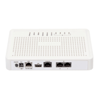
Rear panel. Ports and controls
Power socket (for connection to power line via the supplied
adapter)
1 RJ-45 port for Ethernet 10/100/1000 Base-T interface
USB port for external storage device
RJ-45 console port for local device administration (for
connector wiring, see Appendix A)
4 x RJ-48 ports for Е1 streams (for connector wiring, see
Appendix A)
2 x RJ-48 ports for Е1 streams
3
(for connector wiring, see
Appendix A)
1.6 LED Indication
The current status of the device is shown by the Power, LAN, USB, Alarm, Status, Sync, and E1 indicators
located on the top panel.
Indicator statuses are listed in Tables 3.1 and 3.2.
Table 3.1—LED Indication of the Device Status in Operation
No power supply from 12 V adapter
12 V power supplied to the device
Solid green / blinking green
Port is in the 10/100Base-TX mode
Solid yellow / blinking yellow
Port is in the 1000Base-T mode
USB device is not connected
A high-speed USB device is connected
A low-speed USB device is connected
3
Only one E1 stream is available in an SMG-2 device by default. To activate another one, a special licence is required. For
more information about licences, see section 4.1.19. Licence Renewal
 Loading...