EM TEST Compact NX5
Operating Manual V 1.06 20 / 143
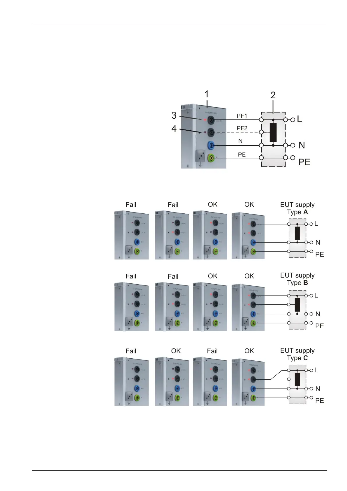
Phase indicator
The phase indication shows the correct connection of the supply to Phase and Neutral input of the compact
NX5. For the generator hardware both, L and N paths are potential free and a reverse connection is not relevant
for the generator operation.
For EUT where it is important that phase and neutral are correct, the LED indication shows the correct phase
connection.
Phase indication
1 compact NX5 generator
2 EUT supply may be a
- direct supply from building or via a
- tapped or variac transformer
3 Phase indication LED illuminated
4 Phase indication LED inactive
Remark: The phase synchronization signal taken
from the L path.
The table below shows all combinations with correct (OK) and incorrect (Fail) supply connections
Type A
Supply to PF1, L, PE
Type B
Supply to PF1, PF2, L, PE
Type C
Supply to PF2, L, PE
 Loading...