EM TEST Compact NX5
Operating Manual V 1.06 50 / 143
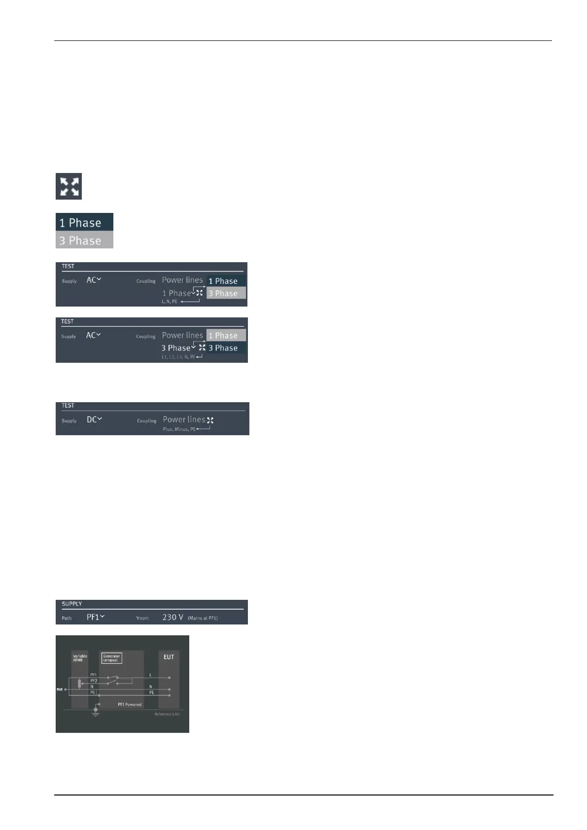
Power configuration for the actual connected EUT
Supply: AC
DC
Coupling: Power lines
Data lines
Phase Filter: Select the used lines
- 1-phase (L, N, PE)
- 3-phases (L1, L2, L3, N, PE)
Coupling Select the used coupling Mode to the selected coupling device
- 1 phase for NX5 device
- 1 or 3 Phase for coupling NX
Supply AC Coupling Power Lines
1 Phase L, N, PE with PE
L, N no PE
3 Phases L1, L2, L3, N, PE Star with PE
L1, L2, L3, N Star no PE (PEN)
L1, L2, L3, PE Delta with PE
L1, L2, L3 Delta np PE
L1, L2, PE Interphase
Lx, Lx, … other combination
Supply DC Coupling Power Lines
Plus, Minus, PE with PE
Plus, Minus no PE
Defines the default supply path to the EUT and the nominal voltage. For DC application the user
needs two DC sources for PF1 and PF2 voltage each.
Path: PF1 Mains voltage from the power grid
PF2 Voltage from the variac or tapped transformer
Vnom: Mains voltage or defined voltage
Path Vnom (mains from the grid)
PF1 100 V, 115 V, 230 V, or any mains voltage
NOTE: PF1 is the default setting for general application for Burst,
Surge and Power Fail testing.
The compact NX generator uses this Vnom voltage as
100% value for Dips test as per IEC 61000-4-11.
 Loading...