4
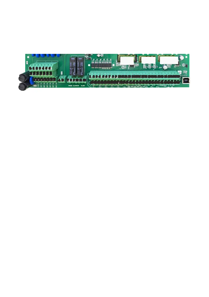
Mainboard Connections.
Unplug instrument from main power supply then perform connections to probes and / or selected outputs by following
the above picture. For easy understanding board has been divided into two parts: Power connections and I/O
connections.
Power Connections:
F1: General fuse (6.3AT)
F2: Circuit fuse (3.15AT)
Main power supply (from 90VAC to 265VAC):
L (live), E (earth), N(neutral)
Setpoint Outputs
(voltage output is the same as for main power supply):
1 - E - N (F1 fuse protected) D1 pH
2 - E - N (F1 fuse protected) Inhibitor
3 - E - N (F1 fuse protected) D1 mV (Biocide 1)
4 - E - N (F1 fuse protected) Biocide 2
5 - E - N (F1 fuse protected) Pre-biocide 1
6 - E - N (F1 fuse protected) Pre-biocide 2
Bleed Valve (Free Voltage Version): 7(N.C.), 8(C), 9(N.O.) Free Voltage contact
General Alarm output: 10(N.C.), 11(C), 12(N.O.) Free Voltage contact
Warning: Connections must be perfomed by qualied and trained personnel only.
L 1 2 3 4 5 6
E E E E E E E
N N N N N N N N
7 8 9 10 11 12
F1
F2
A B
29 30 31 32 33 34 35 36 37 38 39 40 41 42 43 44 45 46 47 48 49 50 51 52 53 54 55 56
1 2 3 4 5 6 7 8 9 1 0 11 12 13 14 15 16 17 18 19 20 21 22 23 24 25 26 27 28
CD Module
pH
Module
]
Power Connections
]
I/O Connections
ORP
Module