Installation, Operation and Maintenance Manual
MAN-02-04-97-0713-EN Rev. 1
October 2019
61
Section 9: Set-Up Routines
Set-Up Routines
The following options can be congured via the local operator interface:
• Dead band: congurable from “position resolution%” to 25.5% of the
maximum position error. The congured value should be great enough to avoid
a "hunting" effect.
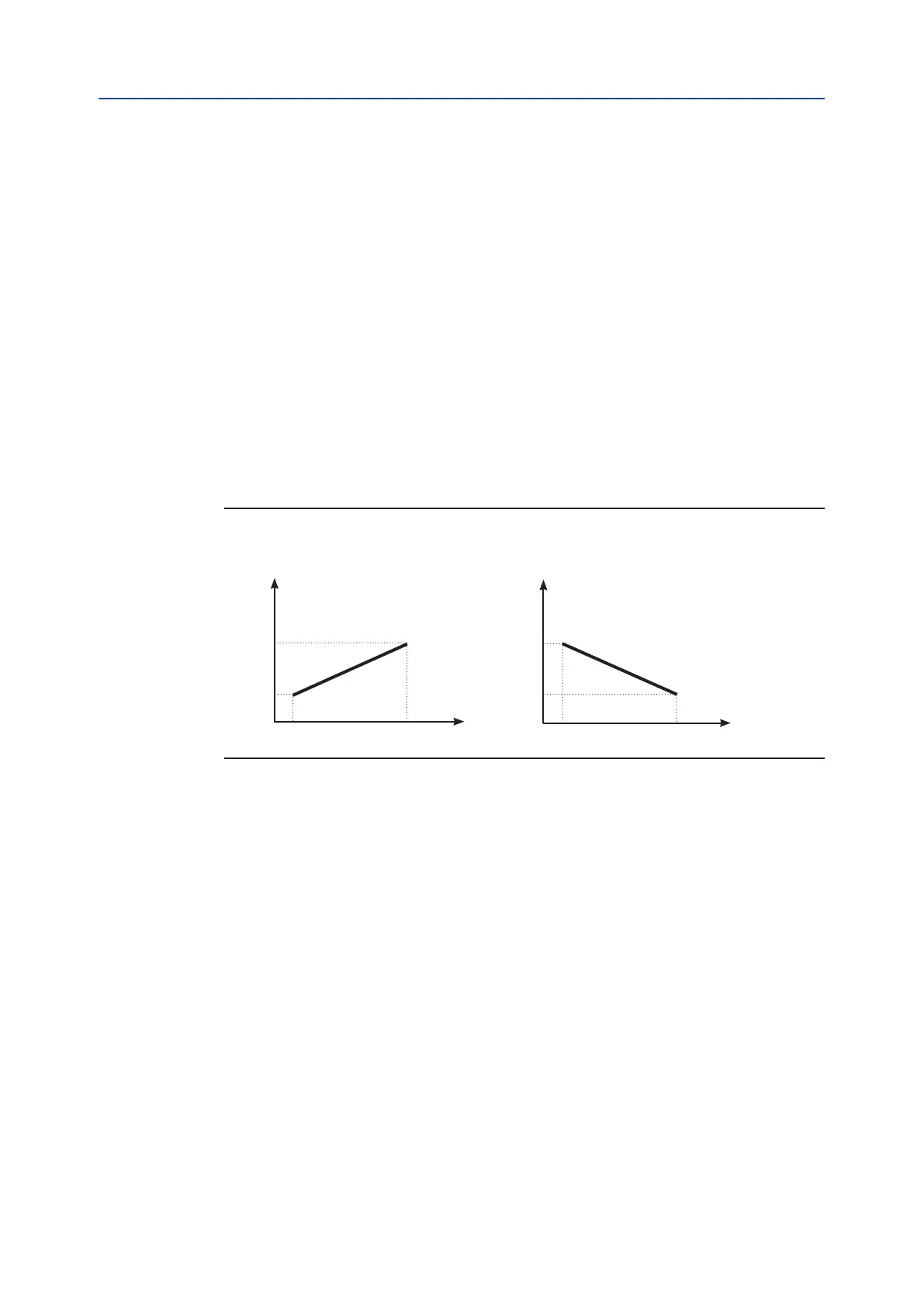
• Polarity of the 4-20 mA position request signal: this allows reversal of the
relationship between the 4-20 mA input signal and the “position request R%”,
according to the following diagrams. This option is not available when the
XTE3000 is set to receive the “position request R%” from the bus.
• Motion inhibit time: this allows adjustment of the length of the delay time
between two cycles of the motor. It can be congured from 1 to 255 seconds and
allows the user to set the maximum number of starts/hour of the motor.
• % MIN and % MAX, 4-20 mA input signal range: this allows a change in the
relationship between the input signal and the position request R%. This function is
useful when a single 4-20 mA signal is used to control the position of 2 valves
(e.g. split range applications). This option is not available when the XTE3000 is set
to receive the “position request R%” from the bus.
Figure 59
100%
100%
0%
0%
20 mA
4 mA
20 mA
4 mA
Input 4-20 mA
Polarity: 4 mA = CL
Input request
Position %
Input 4-20 mA
Polarity: 4 mA = OP
Input request
Position %
The curves below may better clarify the above option:
Example A
With input signal = 4 mA, the position request is 0% and the actuator is driven to close.
With input signal = 20 mA, the position request is 100% and the actuator is driven to open.
With input signal = 12 mA, the position request is 50% and the actuator is driven to reach
position 50%.
Example B
With input signal < 8 mA, the position request is 0% and the actuator is driven to close.
With input signal = 16 mA, the position request is 100% and the actuator is driven to open.
With input signal = 12 mA, the position request is 50% and the actuator is driven to reach
position 50%.
Example C
With input signal = 4 mA , the position request is 100% and the actuator is driven to open.
With input signal = 20 mA, the position request is 0% and the actuator is driven to close.
With input signal = 12 mA, the position request is 50% and the actuator is driven to reach
position 50%.

 Loading...


