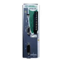
(model CBMS-XXX) has an MS style connector on the motor
end and three wire leads on the amplifier end (see wiring
diagram below).
You must provide a DC power supply rated at +24 VDC with a
2 amp minimum current capacity for the brake. If you use this
voltage source to power other accessories such as I/O or more
than one brake, you must increase its current capability.
Figure 16: Epsilon Brake Wiring Diagram using the
Command Connector
Bottom View
-
+
K1
A
Internal
to Motor
C
B
Red +
Black -
Connected to
grounded
mounting panel.
Single point
PE ground.
11
A2
14
A1
2 Amp
Fuse
Customer
supplied drive
enable contact
Relay:
EMC #BRM-1
24 VDC
Motor
Output #3
Drive Enable
I/O Common
I/O Common
I/O Supply
34
33
32
31
16
17
I/O Supply
J5
1 Amp
Fuse
CBMS-xxx Cable
Artisan Technology Group - Quality Instrumentation ... Guaranteed | (888) 88-SOURCE | www.artisantg.com
 Loading...
