EasyManua.ls Logo

Emerson Liebert PEX+ Series - Set Alarms

Emerson Liebert PEX+ Series
92 pages
Print Icon
To Next Page IconTo Next Page
To Previous Page IconTo Previous Page
Loading...
Chapter 5 iCOM Controller 41
Liebert. PEX+Series Precision Air Conditioner User Manual
Parameters
Default
Setting range
Description
Group 2
S374
LSI
-
Off, On
-
S375
COND 2
-
Off, On
-
S376
COND 1
-
-
-
S379
V_CTRL
Time
Time, Feedb
Valve Control
S380
V_CAL
No
Yes. No
Start Valve Calibration
S381
CAL_STAT
Idle
-
-
S382
CLSD 1
-
0.0-10.0V
-
S383
OPEN 1
-
0.0-10.0V
-
S384
V1FDB
-
0.0-10.0V
-
S385
CLSD 2
-
0.0-10.0V
-
S386
OPEN 2
-
0.0-10.0V
-
S387
V2FDB
-
0.0-10.0V
-
5.7.6 SET ALARMS
The SET ALARMS menu is displayed in nine pages. The first page provides the settings of alarm upper/lower limits
and customized alarms. The other eight pages provide the settings of alarm delay.
Alarm upper/lower limits setting
The alarm upper/lower limits in the SERVICE MENUS are set the same as those in the USER MENUS. For details,
see Table 5-6.
Customized alarms setting
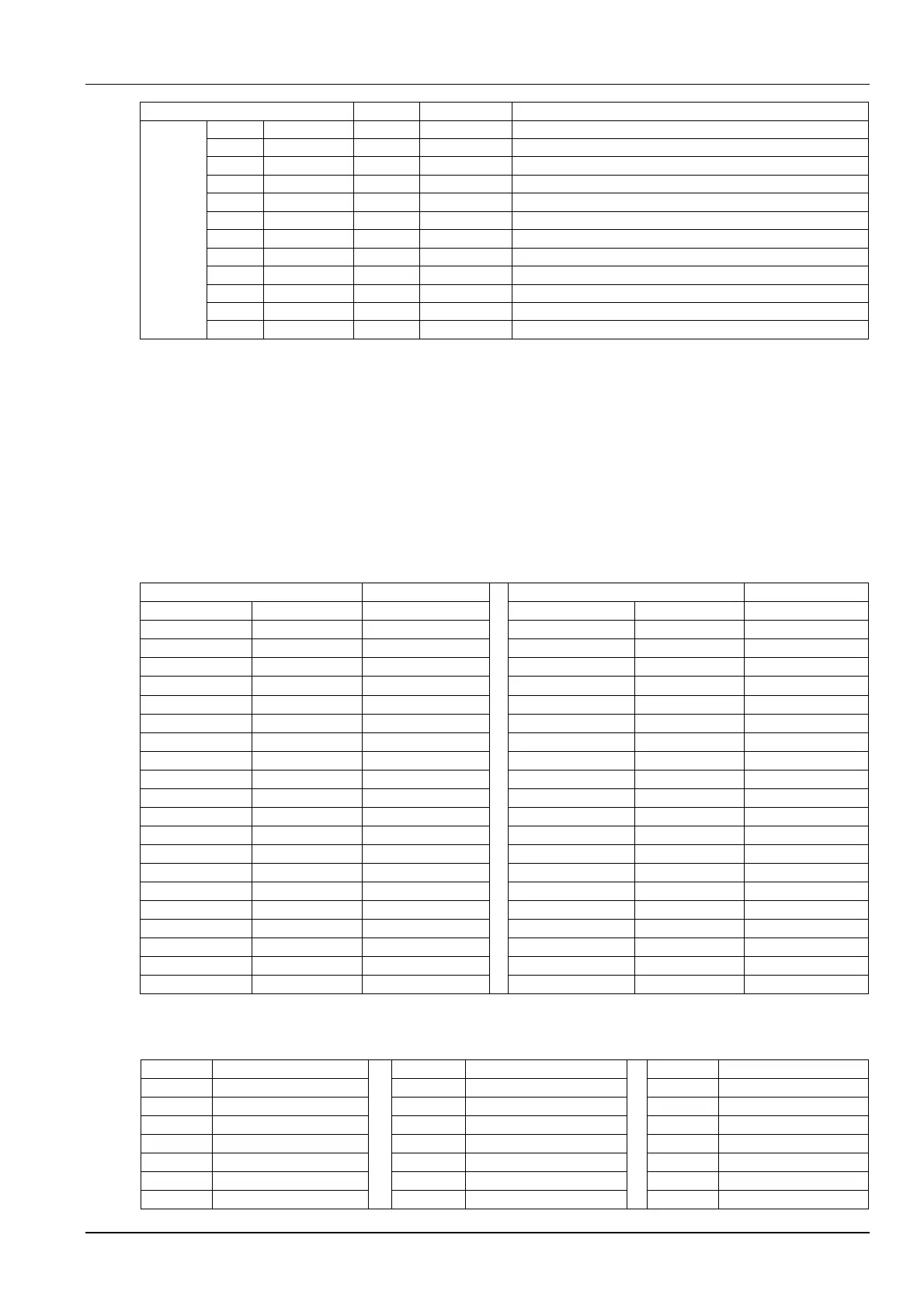
See Table 5-24 for the descriptions of customized alarms setting.
Table 5-24 Descriptions of customized alarms setting
Parameters
Default
Parameters
Default
S202
RTN SNSR
Yes
S216
LO DP
3.9 °C
S202
RET DEL
90 sec
S217
DP A AL
Disabled
S203
HI TEMP
°C
S217
DP A DEL
90 sec
S204
LO TEMP
°C
S218
HI DP A
16.7 °C
S205
HI HUM
60%
S218
HI DP A
2.2 °C
S206
LOW HUM
40%
S219
REM SNSR
Disabled
S207
SENSOR A
No
S219
DP A DEL
180 sec
S207
SE A DEL
90 sec
S220
HI REM
32.3 °C
S208
HI TEMP A
°C
S220
LO REM
12.8 °C
S209
LO TEMP A
°C
S222
EEV ALBD
NC
S210
HI HUM A
%
S224
CUST IN1
WATER
S211
LO HUM A
%
S225
C1 ACT
CLOSE
S21A
FLOCT
0 sec
S226
CUST IN2
WATER
S21B
LOF THRH
10%
S227
C2 ACT
CLOSE
S213
SUP SNSR
No
S228
CUST IN3
WATER
S213
SUP DEL
90 sec
S229
C3 ACT
CLOSE
S214
HI SUP T
23.9 °C
S230
CUST IN4
HEAT A
S214
LO SUP T
10.0 °C
S231
C4 ACT
OPEN
S215
DP AL
Disabled
S232
WA AC AL
No
S215
DP DEL
90 sec
S233
WAT OFF
No
S216
HI DP
15.0 °C
CUST IN1, CUST IN2, CUST IN3 and CUST IN4 can be set to 21 types of input. See Table 5-25 for details.
Table 5-25 Descriptions of types
Types
Description
Types
Description
Types
Description
SMOKE
Smoke alarm
RH+HU
Rht + Hum lockout
RJTVS
HTRJ TVSS
WATER
Water leakage alarm
COMP
Compressor lockout
Fire
Fire Alarm
C PMP
Cooling pump alarm
Call
Call for service
2.Set
2nd Set point
FLOW
Insufficient water alarm
Temp
High temperature alarm
NoP
No Power
G PMP
Standby pump alarm
Air
Air loss alarm
LSI
LSI
STBY
Standby unit alarm
FC L.
FC lockout
Cnd 1
Condensor 1 Fail
C-In1
Customized alarm 1
HeatA
Heater alarm
Cnd 2
Condensor 2 Fail

Table of Contents

Related product manuals