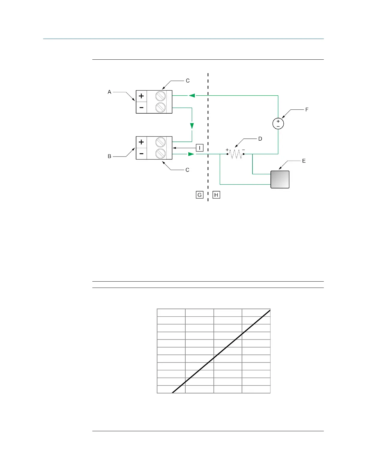
Figure 4-30: Channel A passive (external) and Channel D passive (external) power
A. Channel A mA output
B. Channel D mA input
C. Terminals
D. Maximum loop resistance including 100 ohms (I) for mA input — see Figure 4-31.
E. Signal device
F. 5–30 VDC (maximum)
G. Terminal compartment
H. External to the 5700
I. 100 ohm input resistance
Figure 4-31: Externally-powered mA/HART output: maximum loop resistance
0
100
200
300
400
500
600
700
800
900
1000
1100
0 7.5 15.0 22.5 30.0
B
A
A. Maximum resistance (Ω)
B. External supply voltage (V)
Wiring the channels Installation Manual
April 2022 MMI-20027478
42 Micro Motion 5700 Transmitters with Configurable Inputs and Outputs