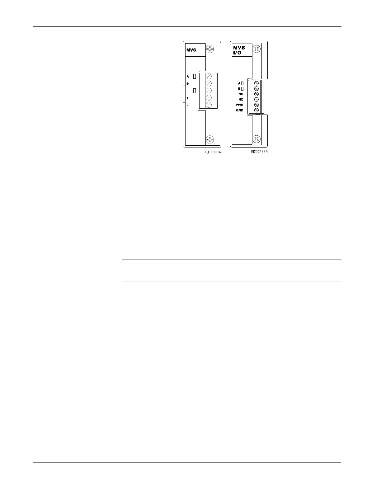
Figure 4-26. MVS and MVS I/O Modules
The MVS I/O module consists of interface electronics that provide the
communications link between the ROC800 and the MVS devices. The
interface electronics controls communications with the sensor module,
provides scaling of process variables, aids calibration, stores operating
parameters, performs protocol conversion, and responds to requests
from the ROC800.
Each MVS I/O module provides the communications interface and the
isolated, short-circuit current-limited power required to connect up to
six MVS sensors.
Note: You can install up to two MVS modules per ROC800. This limit
does not apply to the MVS I/O module.
The MVS I/O module automatically creates six points, one for each of
the six possible MVS channels: 1 – 6 (for one MVS I/O) and 7 – 12 (for
a second MVS module). The system assigns points based on which
module is in the first slot. For example, if an MVS module is in slot 3,
the system automatically assigns it points 1 – 6. If you then install a
second MVS module into slot 1, the system re-assigns points so that slot
1 now holds points 1 – 6 and slot 3 holds points 7 – 12.
The ROC800 allows six MVS devices to be connected on its
communications bus in a multi-drop connection scheme. You must set
the address of each MVS device prior to final wiring of multiple MVS
devices. For proper operation of multiple MVS devices, each MVS
device must have a unique address. None of the addresses can be 240.
For details on MVS configuration, refer to the ROCLINK 800
Configuration Software User Manual (for ROC800-Series) (part
D301250X012) or ROCLINK 800 Configuration Software User Manual
(for ROC800L) (part D301246X012).
Once you set a unique address for each MVS, connect the MVS units in
a multi-drop arrangement. The only requirement for wiring multi-drop
devices is that you tie all like terminals together. This means all the “A”