EasyManuals Logo

Emerson ROC827 User Manual

Emerson ROC827
184 pages
To Next Page IconTo Next Page
To Previous Page IconTo Previous Page
Page #58 background imageLoading...
Page #58 background image
ROC800-Series Instruction Manual
3-4 Power Connections Revised July-2017
A
+ /
B
AUX+ / AUX
C
V
12
LED
D
V
3.3
LED
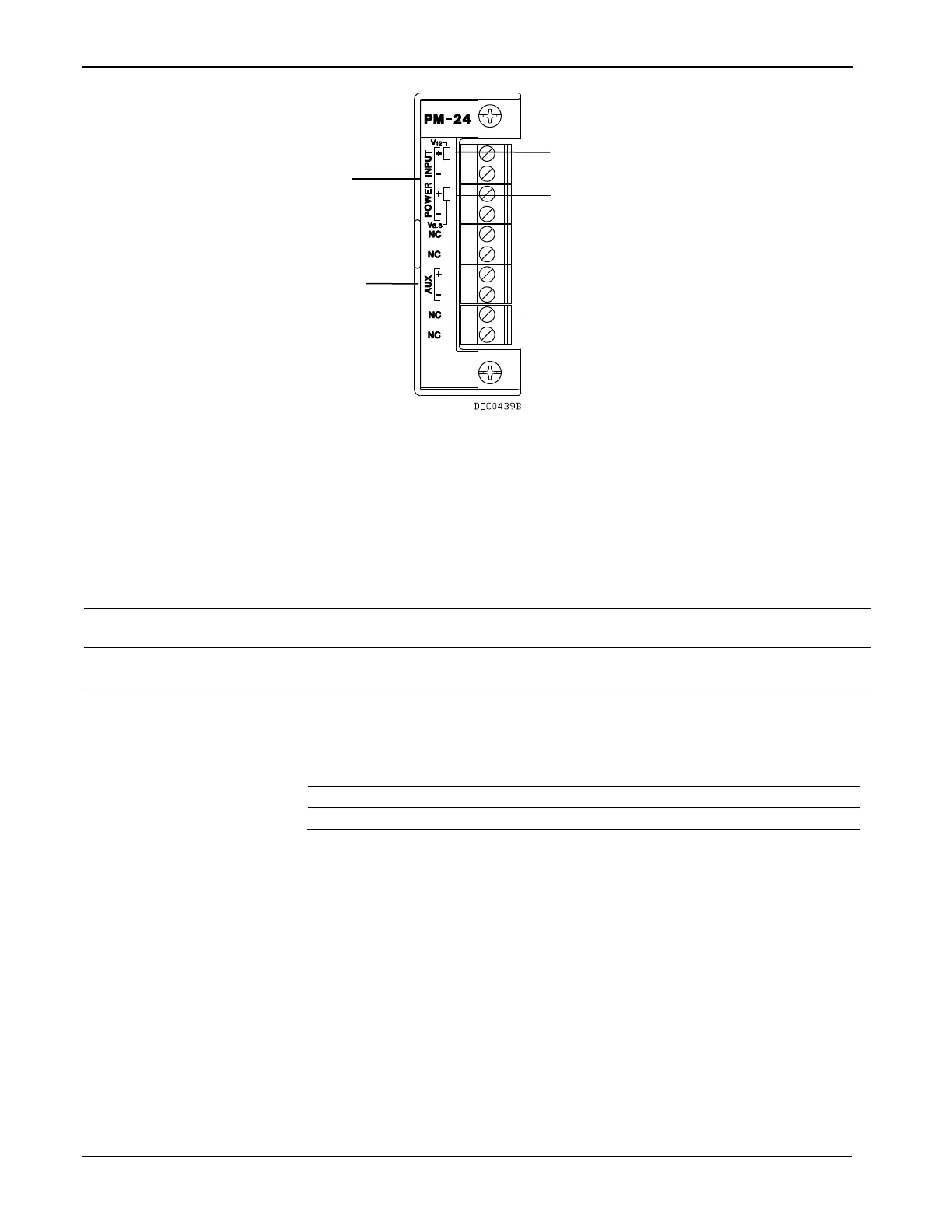
Figure 3-2. 24 Volt dc Power Input Module
Table 3-3. 24 Volt dc Power Input Terminal Block Connections
Terminal Blocks
Definition
Volts DC
+ and
Accepts 24 Volts dc nominal from an AC/DC converter
or other 24 Volts dc supply.
20 to 30 Volts dc
AUX+ and AUX
Supplies reverse polarity protected source voltage to
external devices. Circuit limited.
+12 Volts dc minus 0.7 Volts
dc
Table 3-4. 24 Volt dc Power Input LED Indicators
Signal
LED
V
12
Green LED on when voltage is provided to backplane.
V
3.3
Green LED on when voltage is provided to CPU.
3.1.3 30-Volt DC Power Input Module (PM-30)
Using the PM-30, the ROC800 can accept up to 30 Volts dc (nominal)
input power from an AC/DC converter or other 30 Volts dc supply
connected to the + and terminals. Connect the input power to either or
both of the + and channels. The PM-30 module does not have CHG
terminals for monitoring a charging voltage, and does not monitor the
input voltage for alarming, sleep mode, or other monitoring purposes.
The module has two LEDs that indicate voltage is received at the
backplane and the CPU (see Figure 3-3 and Tables 3-3 and 3-4).
The module uses 3.3 Volts dc switching power to provide power to the
I/O and communications modules installed in the ROC800 and any
D
C
B
A

Table of Contents

Questions and Answers:

Question and Answer IconNeed help?

Do you have a question about the Emerson ROC827 and is the answer not in the manual?

Emerson ROC827 Specifications

General IconGeneral
BrandEmerson
ModelROC827
CategoryController
LanguageEnglish

Related product manuals