ROC800-Series Instruction Manual
3-2 Power Connections Revised July-2017
backplane. The ROC800 requires 11.5 to 14.5 Volts dc for proper
operation.
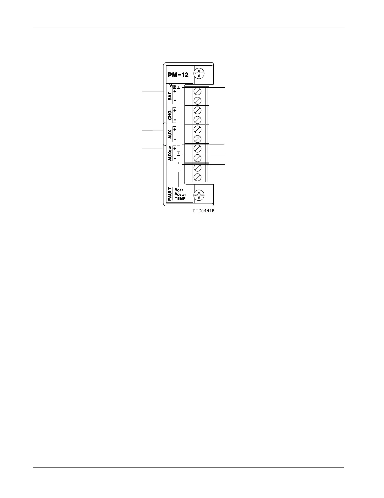
Figure 3-1. 12 Volt dc Power Input Module
The CHG+ and CHG– terminals comprise an Analog Input channel that
allows you to monitor an external voltage between 0 to 18 Volts dc. For
example, you can connect a solar panel upstream of the solar regulator
to monitor the output of the solar panel. This allows you to compare the
System AI Point Number 2 for the charging voltage (CHG+) to the
actual battery voltage (BAT+) System AI Point Number 1 and take
action as required. The module has a low-voltage cut-off circuit built-in
to guard against draining power supply batteries. Refer to Automatic
Self Tests in Chapter 1, General Information.
Use the AUX+ / AUX– terminals to supply reverse polarity protected
source voltage to external devices, such as a radio or solenoid. Use the
AUX
SW
+ / AUX
SW
– terminals to provide switched power for external
devices. The AUX
SW
+ is turned off when the ROC800 detects a
software configurable voltage at the BAT+ / BAT– terminals.
Table 3-1 details the specific connection information for the 12 volt dc
(PM-12) Power Input module. Table 3-2 indicates the LED fault
indicators.