ROC800-Series Instruction Manual
Revised July-2017 Power Connections 3-9
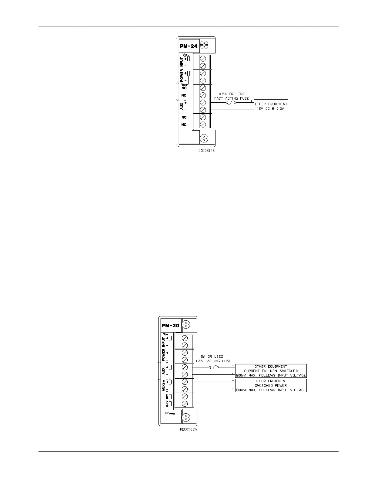
Figure 3-8. Auxiliary Power Wiring for PM-24 Module
For the 30 volt dc Power Input module (PM-30), the auxiliary output
follows the voltage located at BAT+ minus ~1.0 Volts dc, which is the
protection diode voltage drop. For example, if the BAT+ voltage is 13
volts dc, then AUX+ is ~12.3 Volts dc.
For the PM-30 Power Input module, AUX+ / AUX– is always on and is
internally current-limited by a .9 Amp Positive Temperature Coefficient
(PTC).
If you need to cycle power to the radio or other device to reduce the
load on the power source (a recommended practice when using
batteries), use a Discrete Output (DO) module to switch power on and
off. (The PM-12 and PM-30 module’s on-board AUX
SW+
and AUX
SW–
terminals perform this function.) Refer to the ROCLINK 800
Configuration Software User Manual (for ROC800-Series) (part
D301250X012) or the ROCLINK 800 Configuration Software User
Manual (for ROC800L) (part D301246X012).
Figure 3-9. Auxiliary Power Wiring for PM-30 Module